 Guns, Politics, Gunsmithing & Reloading Gunsmithing
 Go | New | Find | Notify | Tools | Reply |
| Mechanical drawings for barrel shanks and parts | Login/Join |
| One of Us |
I'm not sure how many people do this. But as my vision has progressively gotten worse, I have replaced my nose with a webcam when milling small parts where it is necessary to work to sight and not to numbers. It's actually a pretty cheep solution to the problem as webcams can be had for about $30 on eBay and there are hundreds of free software programs on GooglePlay that let you run them on your android phone or tablet. I have an OtterBox cover on my tablet and phone which is a handy option. The white marks that you can see on the plastic OtterBox are where chips have melted into the cover. The only other things you need is to re-purpose one of you micrometer stands for the camera and buy a $5 adapter that goes from the USB plug on the camera to the micro-USB in the phone or tablet. 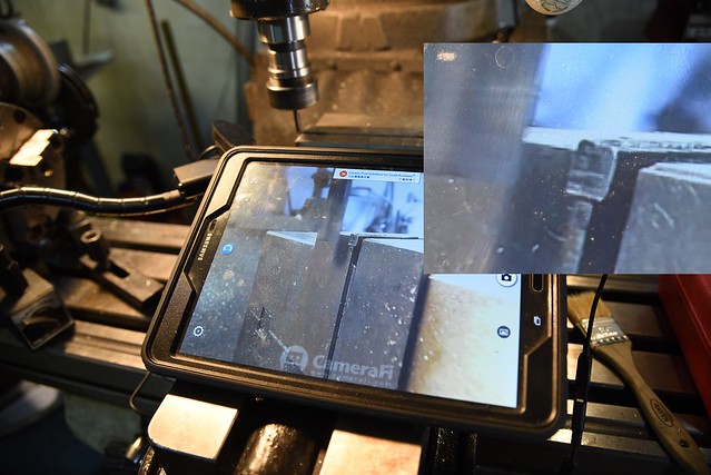 mill cam by Rod Henrickson, on Flickr mill cam by Rod Henrickson, on FlickrWhen I was a kid. I had the stick. I had the rock. And I had the mud puddle. I am as adept with them today, as I was back then. Lets see today's kids say that about their IPods, IPads and XBoxes in 45 years! Rod Henrickson | |||
|
| One of Us |
I put this post in another thread but decided to drop it here too showing how to use a smooth jaw vise as a file guide so that only the foot of the dovetail is cut and is kept square. Safe sided dovetail files do work after a fashion but they will eventually either dive or climb depending on where the teeth end on the edge of the file. The sure way to keep everything square and neat is to use a file guide. The two little planer blades are used to align the flat on the sight to the flats of the hardened vise jaws. Simply press them together and slightly down against the dovetail and tighten the vise. The novelty of them is that the sight can be filed and then put back into the vise time and time again as you cut. The file will simply skate over the hardened jaws. It's a very cheap and foolproof filing guide and I have used this method a lot when the mills are occupied with something else. 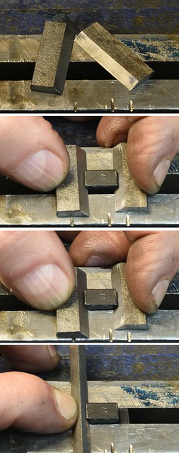 Sight File Guide by Rod Henrickson, on Flickr Sight File Guide by Rod Henrickson, on FlickrWhen I was a kid. I had the stick. I had the rock. And I had the mud puddle. I am as adept with them today, as I was back then. Lets see today's kids say that about their IPods, IPads and XBoxes in 45 years! Rod Henrickson | |||
|
| One of Us |
Canadian firearms laws are just as convoluted as American laws. One of the grey areas right now is the SKS and it's mag conversions. Under Canadian law, full auto rifles and rifles which are variants of full autos are illegal to own. Sometimes. Variant, loosely means that it was manufactured as a full auto and then later stopped down to semi automatic fire. Also, center fire semi automatic rifles which hold more than 5 rounds are illegal. Sort of. The SKS is NOT a variant of a full auto. Yes, at a later date the SKS was re-engineered to fire full auto but the base rifle was designed and first manufactured as semi auto fire only. So legally the can be owned in Canada providing the magazines are pinned to hold 5 rounds before entering the country. Removing the pin to make it hold and mare than 5 rounds is illegal. Now it gets confusing. The Canadian government chose to make 1000 little laws to determine if a gun was or was not legal in Canada. A number of criteria like a check list of sorts determine what class a firearm will fall into. The SKS is quite legal to own with it's pinned magazine or even if you remove the pinned magazine entirely. Rather than simply saying that a semi automatic rifle that holds more 5 rounds, or converting a semi auto rifle to hold more than 5 rounds was illegal, they chose to ban high all capacity magazines that were made for semi auto rifles. It seems really simple if you happen to be an idiot. Or a bureaucrat. The grey area suddenly comes into place when some cowboy takes a magazine that is manufactured for a pump, leaver action or bolt action which holds 40 million rounds (which is perfectly legal) and converts his SKS or other legally owned semi auto to function with it. The same applies to pistol mags. All semi auto pistols in Canada are limited to 10 rounds. But of course there is no provision in the law to stop your local mall commando from adapting his semi auto rifle to accept 10 round pistol magazines. When people first began asking me to convert the SKS to 10 round mags I simply said no ! It was a grey area and I tend to stay clear of those sorts of things. After a couple of years of saying (no) I contacted the RCMP, Regional Firearms Intelligence Coordinator (Our local gun-narc) and asked him quite pointedly if what was happening was legal or not? He researched it and came back to me that it was indeed one of those loop holes in the law, that for the time being was perfectly legal to do. His feelings were that for the time being, it was fine to do the conversion but in the near future the RCMP would sit down and find a way to close the loophole. At that point, people who had done the conversion would have to convert them back to comply with the closed loophole. Well, 5 years have pasted and it seems that the RCMP have simply chosen to ignore the conversion rather than make it illegal and while I'm probably the last gunsmith in Canada to do so, I have finally started doing them. Below are some photos of the conversion and dimensions. Because there are so many variants of the SKS and the tolerances and dimensions change so much from one manufacturer and run to the next, the makers of these conversions do not offer any hard dimensions. And they are correct. Every conversion is a one off and slightly different than the next. It has been my experience that none of these conversions work reliably if more than 7 rounds are put into the magazine and a lot of them will only work with hard ball, pointed, heavily crimped or glued in bullets. Despite what the manufacturers claim. Yes, the odd one works right out of the box and yes some of them can be made to work if you dick with the mag spring and follower but advise your customers that you don't guaranty function ! The dimensions I have shown will work, some of the time ! ! ! Govern yourselves accordingly and use them at your own risk. And to those in Canada. Remember that the RCMP or the Canadian government could close this grey area at any time. The modifications are permanent and non-reversible so you may simply be giving your SKS to the RCMP at some point down the road or owning a non-functionable firearm after you have to remove the conversion to comply with the law. I will update these dimensions and cuts as and if I find some more reliable. 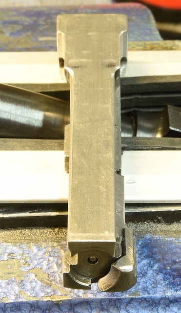 sks1 by Rod Henrickson, on Flickr sks1 by Rod Henrickson, on Flickr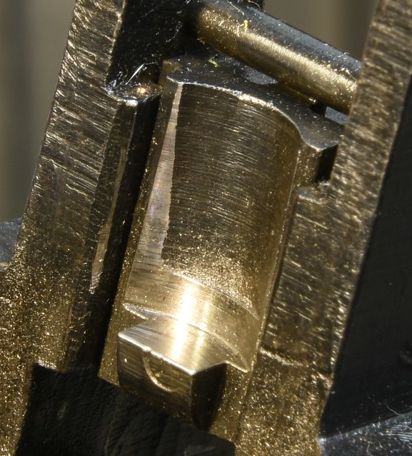 sks2 by Rod Henrickson, on Flickr sks2 by Rod Henrickson, on Flickr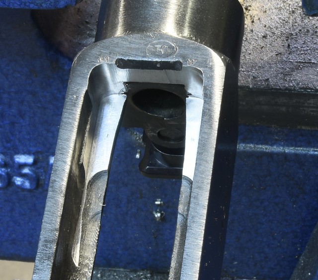 sks3 by Rod Henrickson, on Flickr sks3 by Rod Henrickson, on Flickr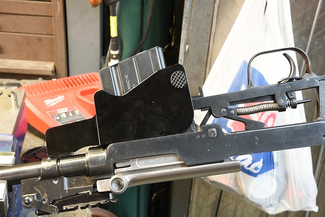 sks4 by Rod Henrickson, on Flickr sks4 by Rod Henrickson, on Flickr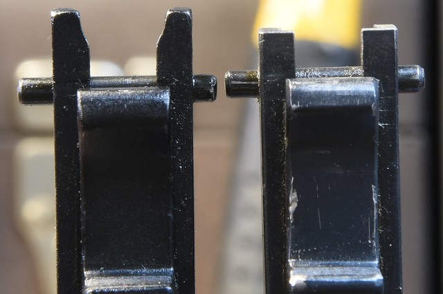 sks5 by Rod Henrickson, on Flickr sks5 by Rod Henrickson, on Flickr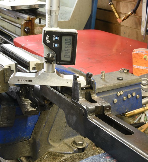 sks6 by Rod Henrickson, on Flickr sks6 by Rod Henrickson, on Flickr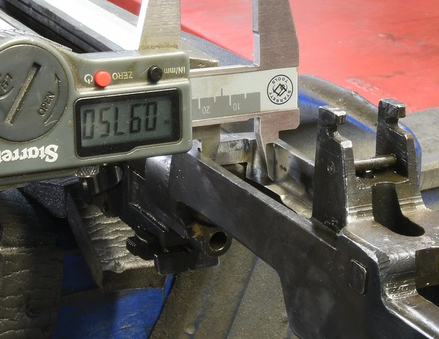 sks7 by Rod Henrickson, on Flickr sks7 by Rod Henrickson, on Flickr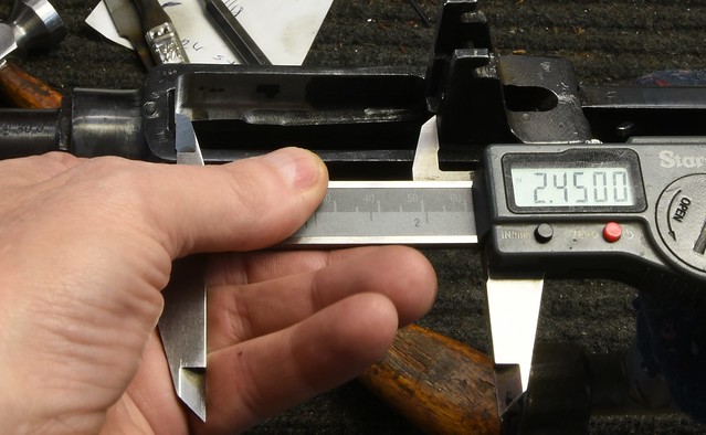 sks8 by Rod Henrickson, on Flickr sks8 by Rod Henrickson, on FlickrWhen I was a kid. I had the stick. I had the rock. And I had the mud puddle. I am as adept with them today, as I was back then. Lets see today's kids say that about their IPods, IPads and XBoxes in 45 years! Rod Henrickson | |||
|
| One of Us |
I've heard a lot of arguments for and against. But, to this day I still cut toe holds in stocks when bedding guns. Yes it is a lot more work even with carbide tooling, but I have seen far to many bedding jobs pull free after a few years. Especially those often refereed to as skin bedding. I still rough up the surfaces with a wire brush and wipe everything down with lacquer thinner to degrease and soften the finish but I feel a lot better knowing the toe holds are there. About 3 or 4 years ago I had to plumb some oil lines in a crank case for a local hotrod shop and to do it I had to buy some long reach ER collet extensions. I thought that they would be single use tools and charged accordingly. As it turns out I wouldn't trade them for the world for work like this. They give you a huge throat to see and work in and no more crashed collets into pistol grips and other such protrusions. 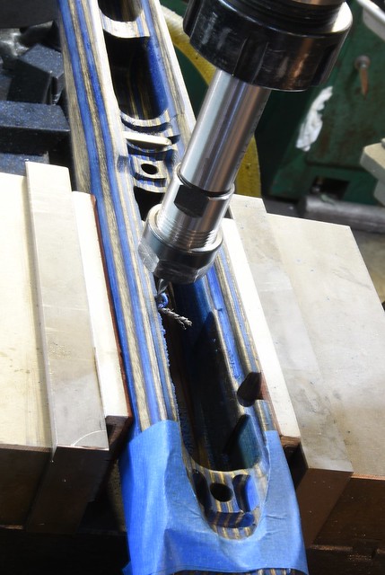 toe holds bedding tikka by Rod Henrickson, on Flickr toe holds bedding tikka by Rod Henrickson, on Flickr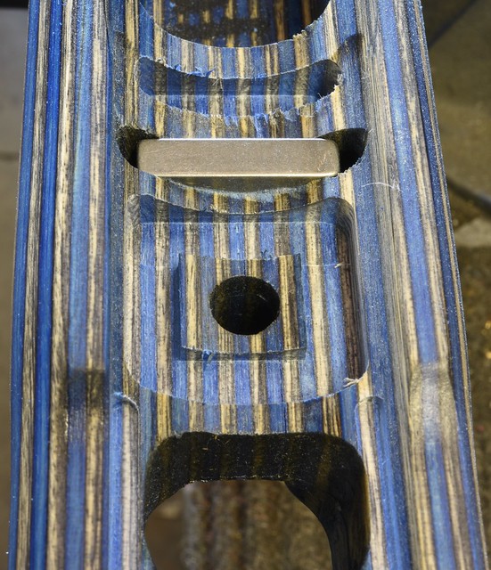 toe holds bedding tikka3 by Rod Henrickson, on Flickr toe holds bedding tikka3 by Rod Henrickson, on Flickr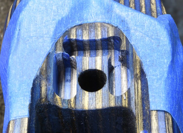 toe holds bedding tikka2 by Rod Henrickson, on Flickr toe holds bedding tikka2 by Rod Henrickson, on FlickrWhen I was a kid. I had the stick. I had the rock. And I had the mud puddle. I am as adept with them today, as I was back then. Lets see today's kids say that about their IPods, IPads and XBoxes in 45 years! Rod Henrickson | |||
|
| One of Us |
I finally figured out what I'm going to do with my Mauser. I'm keeping it! 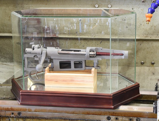 Glass House Mauser by Rod Henrickson, on Flickr Glass House Mauser by Rod Henrickson, on FlickrWhen I was a kid. I had the stick. I had the rock. And I had the mud puddle. I am as adept with them today, as I was back then. Lets see today's kids say that about their IPods, IPads and XBoxes in 45 years! Rod Henrickson | |||
|
| One of Us |
Over the years I have spent on these forums I have probably heard 50 guys, whining and crying because their cross slide nut is worn out and the parts are no longer available. I have always said: "You have a lathe and mill and you can thread and chamber a gun but you can't go down and buy a piece of bronze or brass, order a $60 tap and make a simple cross slide nut?" Most of the time the conversation goes on for a month about tinning this, modifying one of those and so on and in the end they just suffer with the loose nut and slap for the next 20 years. Well karma is a bitch and I finally got caught. So (HELLO TOKYO) and I ordered a 5/8 x 10 TPI left hand Acme tap for the huge sum of $45 USD including shipping on a slow boat from China, bought a piece of brass and 3 hours on the mill later, I have a nice, tight, new, cross slide nut ! So, bite-me-where-I-stink ! 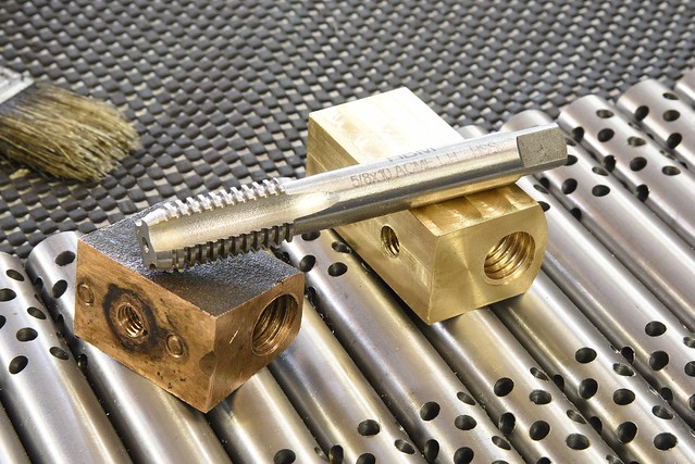 Cross Slide Nut by Rod Henrickson, on Flickr Cross Slide Nut by Rod Henrickson, on FlickrWhen I was a kid. I had the stick. I had the rock. And I had the mud puddle. I am as adept with them today, as I was back then. Lets see today's kids say that about their IPods, IPads and XBoxes in 45 years! Rod Henrickson | |||
|
| One of Us |
Just bedding a Ruger M77 and snapped a picture. I never bed with the floor plate / trigger guard simply because of the 1/2 hour of cleanup that's require and the risk of scratching those parts if they get stuck. Normally I make heavy bars drilled and recessed to emulate these parts and I just wire wheel off any left over glue when I'm done. With the M77 I made a couple plates which are milled to take the place of the floor plate and trigger guard. They have worked well for 20 years so I have never bothered to make a fancy bar. 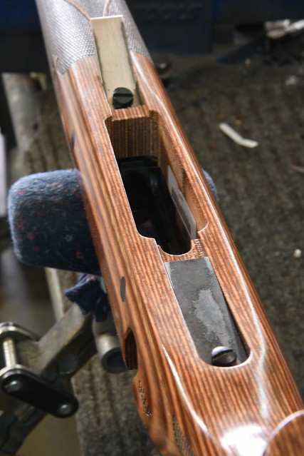 Ruger 77 Bedding Plates by Rod Henrickson, on Flickr Ruger 77 Bedding Plates by Rod Henrickson, on FlickrWhen I was a kid. I had the stick. I had the rock. And I had the mud puddle. I am as adept with them today, as I was back then. Lets see today's kids say that about their IPods, IPads and XBoxes in 45 years! Rod Henrickson | |||
|
| One of Us |
Some months ago, an F Class shooter brought a Defiance in for a new barrel and he happens to be a body man by trade and wanted to do the bedding and painting of the stock himself. He's actually a pretty bright kid and before he dropped it into the glue he brought it in to show me just so I could check to make sure that he had no pressure points that would spring the action and that he hadn't missed any other little problems. He was pretty proud of how he had spent 20 minutes with a bit of sand paper on a stick getting the carbon stock roughed up so that the glue would stick. Just to piss him off I suppose, I grabbed one of my small wire brushes and rouged up the entire barrel channel in less than a minute. After I get the toe holds cut on the mill, I always take a clean, wire brush and scrub everything really well. Then, about 20 minutes before the glue goes in I wipe it all down with lacquer thinner to remove any dust and to soften any remaining finish. The glue generally sticks like flies to a gut wagon. 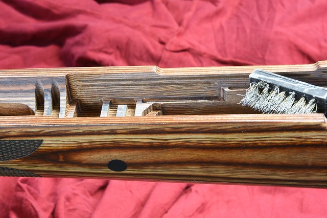 wire brush by Rod Henrickson, on Flickr wire brush by Rod Henrickson, on FlickrWhen I was a kid. I had the stick. I had the rock. And I had the mud puddle. I am as adept with them today, as I was back then. Lets see today's kids say that about their IPods, IPads and XBoxes in 45 years! Rod Henrickson | |||
|
| One of Us |
While side by sides are not so bad. Over and unders can be a real pain in the ass to hold in the vise while stripping them. Some guys fight with them held sideways and get a sore back while others contend with them sliding all over the bench and scratching the hell out of them. Others eventually get smart and cut OU Vise Blocks out of pieces of aluminum. There are basically 2 sizes. One for large frame, 12 and 16 gauge and one for small frames. Make them a bit undersized so they will fit all receiver types. I have used wooden blocks in the early years. While they are better than nothing, it's hard to get them tight enough and they crush and wear out quickly. You make the aluminum ones ONCE ! 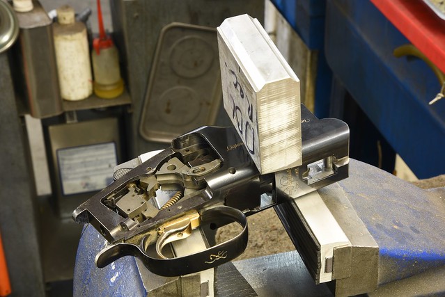 OU Block1 by Rod Henrickson, on Flickr OU Block1 by Rod Henrickson, on Flickr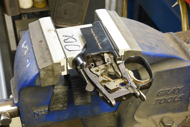 OU Block2 by Rod Henrickson, on Flickr OU Block2 by Rod Henrickson, on FlickrWhen I was a kid. I had the stick. I had the rock. And I had the mud puddle. I am as adept with them today, as I was back then. Lets see today's kids say that about their IPods, IPads and XBoxes in 45 years! Rod Henrickson | |||
|
| One of Us |
A lot of people have trouble installing the ejectors in the Remington 870s. The main problems seem to be getting the rivets to tighten up and hold the ejector solid and facing the rivets off after without destroying the receiver. The whole trick to the riveting is actually in the anvil and the clamping of the receiver. I know some guys that use heavy bench block without clamping and it does work most of the time. But not as well as a massive piece of steel or a real anvil. One of my competitors has a nice setup. He actually rivets them in his Cincinnati mill. He sets a piece of paper on the big flat of his Kurt and lowers the spindle onto a hard hockey puck placed onto the receiver and then goes after the rivets. I use a 2x2 bar of steel that I normally use for clamping stocks into the mill at various angles for drilling and milling. I put a piece of paper between the receiver and the bar to protect the bluing or paint and then use a couple of common clamps to hold the receiver in place. I use a couple of rubber faced, magnetic vise jaws to protect the receiver finish. The primary cause of the rivets not wanting to tighten properly is the receiver bouncing against the anvil surface. Eliminate the bounce, eliminate rivets that won't tighten. 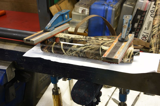 clamp steel bar by Rod Henrickson, on Flickr clamp steel bar by Rod Henrickson, on FlickrThe best thing to do when doing the first one is to buy a set of the riveting tools to get to understand them and and the dimensions. They don't last forever so you will have to buy new ones down the road, or start making them yourself. They are simple to make if you have a lathe and some drill rod. The tool with the deep hole is used to rivet the ejector to the receiver with the front rivet, before the ejector spring is installed. The ejector spring, which is installed last is set using the tool with the concave face. The Brownells tools are actually rectangular faced and do help keep the heads of the rivets centered while creating the heads. After 35 years of doing it I simply watch the shape of the head as it's created and angle the punches to keep them centered. If it's your first time, the Brownells tools will make things a lot easier. The cutting tool is used to reclaim the front rivet if only the ejector spring needs to be replaced. You can usually only reclaim that rivet once and then it gets to short. 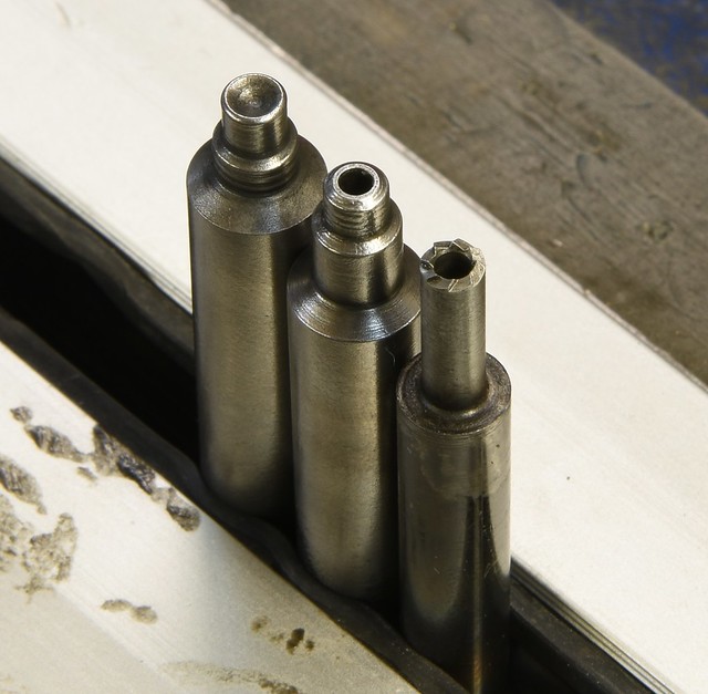 rivet tools by Rod Henrickson, on Flickr rivet tools by Rod Henrickson, on FlickrThe rear ejector rivet is set with the flat nosed tool which I no longer own or use and is not shown. I normally put the rear rivet in the lathe and center drill it sightly. I then seat them with a blunt center punch. They seem to seat just as tight with a lot less beating. 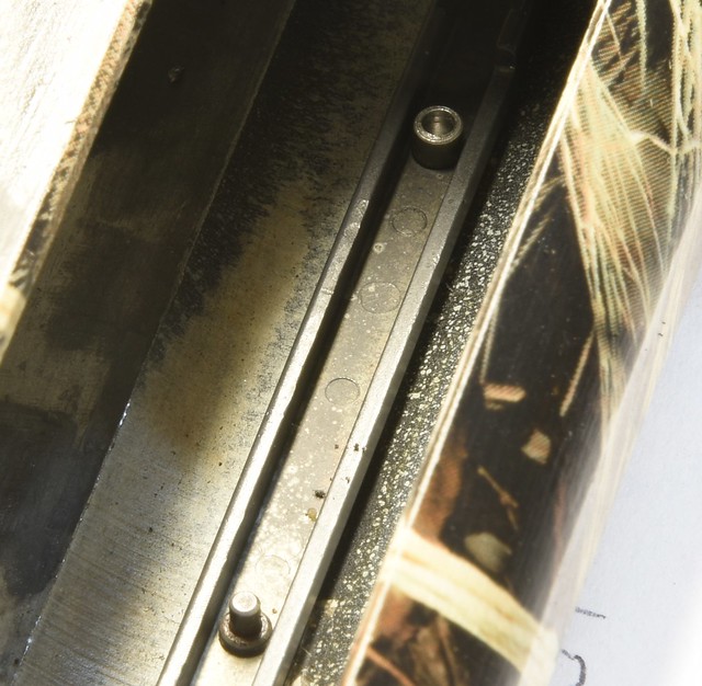 drill rivet by Rod Henrickson, on Flickr drill rivet by Rod Henrickson, on FlickrThe best way to face the rivets is to hold the receiver against the plate of the belt sander and then reblue the receiver. With no bluing setup the simple method is to put the receiver in the mill and center on the rivet with a slot mill the same diameter as the rivet and plunge face them flat to the receiver and cold blue the heads. No mill? In that case a piece of masking tape over the receiver and then carefully draw file the heads down. 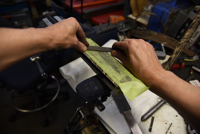 draw file rivet by Rod Henrickson, on Flickr draw file rivet by Rod Henrickson, on FlickrThen using the same method, sand them the last little bit. It will get you within .002 inch and you can then cold blue the heads. Be very careful. If you break through the tape you may be buying the guy a new receiver. Most customers are not to understanding. I have bought guys the odd new receiver using all of this method over the last 35 years so I build $50 insurance into the cost of every job. Govern yourself accordingly. 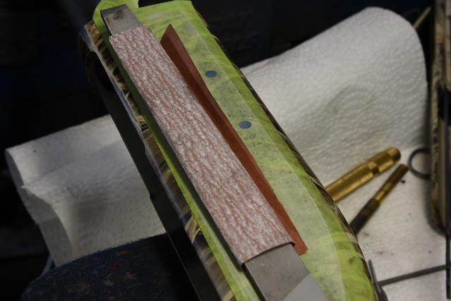 polish rivet by Rod Henrickson, on Flickr polish rivet by Rod Henrickson, on FlickrWhen I was a kid. I had the stick. I had the rock. And I had the mud puddle. I am as adept with them today, as I was back then. Lets see today's kids say that about their IPods, IPads and XBoxes in 45 years! Rod Henrickson | |||
|
| One of Us |
One of the things that we are forever doing in this industry is trimming 6x48 and 8x40 screws to specific lengths to keep them from bottoming out or going completely through the receiver and interfering with the operation of the firearm. I have several sets of hemostats with threads cut into the jaws for holding screws for quicky jobs. But for times when I need multiple screws all of the same length, I have some little fixtures that I made years ago for just that task. They are made from drill rod and the noses are hardened as hard as possible so that the threads inside will last, hopefully forever. The hollow tube, or shank at the back is annealed to blue so that it isn't accidentally crushed in the lathe chuck. (that did happen to me on one I made) Well, my 6x48 fixture finally took a powder or left in someones pocket after 20 years and after 3 weeks of doing without, I finally broke down and made another. The pictures are pretty self explanatory and everyone should have enough on the ball to be able to make them if they wish, without dimensions. The screw is simply dropped in the back and tightened solid. The depth of the threads is about 6 threads which is just a touch less than the common, shortest Weaver screw. That will allow enough that you can use it to cut the tapered end off the short Weaver screws. After the screw is locked in, the fixture inserted into the chuck with the flange against the jaw noses, tightened in and the screw is cut to whatever length you want. The Z axis location is noted on the hand wheel or DRO and cutting more, to the exact, same length is a snap. The angle of the nose of the drill bit used to bore out the hollow part closely matches that of the Weaver fillister screws so repeatability is excellent. As long as you don't lose them or crash them in the lathe they should last the average guy about 20 life times. ADD NOTE: When you back the screw out, the threads in the hardened nose of the fixture will reform any of the thread on the end of the screw that has been rolled over during the trimming on the lathe. If you wish you can back the screw out until only the last thread is exposed and hold it against a wire wheel to knock off the tail from the last thread. 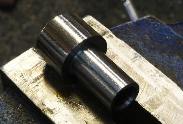 Weaver Screw Trimmer1 by Rod Henrickson, on Flickr Weaver Screw Trimmer1 by Rod Henrickson, on Flickr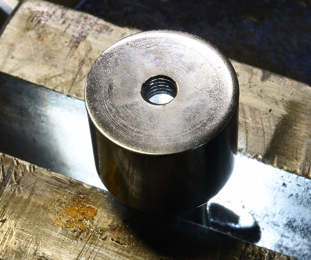 Weaver Screw Trimmer2 by Rod Henrickson, on Flickr Weaver Screw Trimmer2 by Rod Henrickson, on Flickr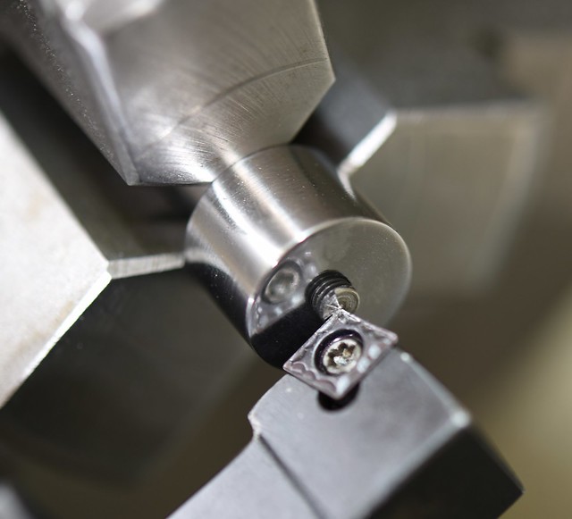 Weaver Screw Trimmer3 by Rod Henrickson, on Flickr Weaver Screw Trimmer3 by Rod Henrickson, on FlickrWhen I was a kid. I had the stick. I had the rock. And I had the mud puddle. I am as adept with them today, as I was back then. Lets see today's kids say that about their IPods, IPads and XBoxes in 45 years! Rod Henrickson | |||
|
| One of Us |
I had a young guy in who it seems is into 3 Gun. I didn't know we had 3 Gun in Canada. The fact of the matter is, what I know about 3 gun and it's guns could be written on the back of an aspirin with a 4 inch paint brush. So, not-so-much ! At any rate he wanted an oversized button installed on the slide release of his Benelli M2 (HO HUM, Bother!) And he also wanted the mag well opened up for double feeding. Now this was a new one to me. We talked about it for a bit and I sort of got the gist of it and then spent about 3 hours on line downloading photos of what the American gunsmiths have been doing about this. Well, it would seem that none of the REAL gunsmiths are doing much of this at all. It does seem however, that Bubba is doing a hell of a lot of it. The stuff I saw on line and the how-to-do-its frightened the ever living shit out of me. As far as I'm concerned there are a lot of very fucked up Benelli M2s out there right now. But, between downloading photos and loading them into Autocad to get some basic dimensions and after talking to a couple of my falcons in the US who have a basic understanding of it, I took it on and this is the result. The radius cut at the front was done with a 3/4 inch carbide ball mill (you have to climb mill to get a finish in the gummy material) The depth of the cut with the ball mill is exactly .250 inch from the bottom of the front of the receiver. The angled cut to let your hand slip by after palming the shells in was simply an eyeball cut with a slot mill until it looked about right. The long cuts on the bottom of the receiver were done with a carbide slot mill and after doing the math from the end of the trigger unit to the center of the ball mill cut I set the sine bar at exactly 2 degrees and it worked out perfect. I made a 1/64th inch, 45 degree cut on the inside of the cuts to break the sharp edges. I don't know if it's right, but the customer seemed happy and the customer is always right. ADD NOTE: To anyone who decides to do this sort of work. Try to sell the customer on one of the after market carriers. Or weld up the notch and lengthen the carrier slightly. Even with my brief amount of time spent playing with this one, I can assure you that it is indeed a: "FINGER TRAP" that was probably designed by an Italian version of Satan! It will hurt you. It will hurt you, BAD. 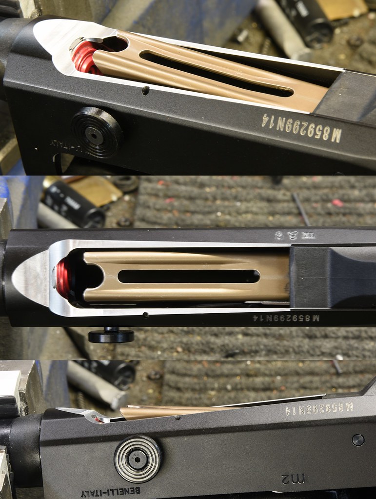 Benelli M2 3 gun mod by Rod Henrickson, on Flickr Benelli M2 3 gun mod by Rod Henrickson, on FlickrWhen I was a kid. I had the stick. I had the rock. And I had the mud puddle. I am as adept with them today, as I was back then. Lets see today's kids say that about their IPods, IPads and XBoxes in 45 years! Rod Henrickson | |||
|
| One of Us |
I had a customer who had his Norinco DA50 fire from an open bolt. As near as we can tell the firing pin return spring in the gun is quite weak and when the bolt was rammed shut, extra hard on a tight hand load the firing pin continued forward under kinetic energy, over powered the spring and fired the round. As the lugs wear not engaged, it blew the bolt back and outward and the outward movement probably kept operator damage to a minimum. Damage to the gun was quite heavy and the entire bolt was a right off and had to be aborted from the gun in pieces in the mill. The rest of the upper and lower was basically unharmed save a gouge in the receiver which was caused by the bolt handle. Ironically, damage to the operator was minimal. The case was totally destroyed and the bullet did exit the barrel so chamber pressures were probably in excess of 20,000 PSI. 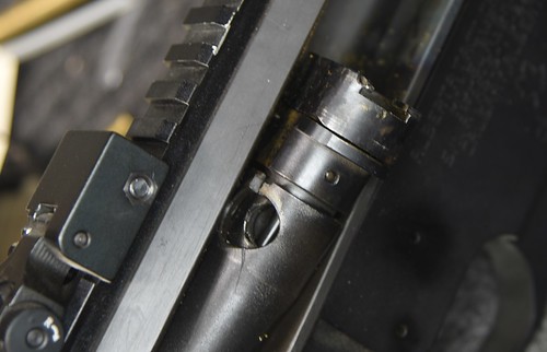 norinco da502 by Rod Henrickson, on Flickr norinco da502 by Rod Henrickson, on Flickr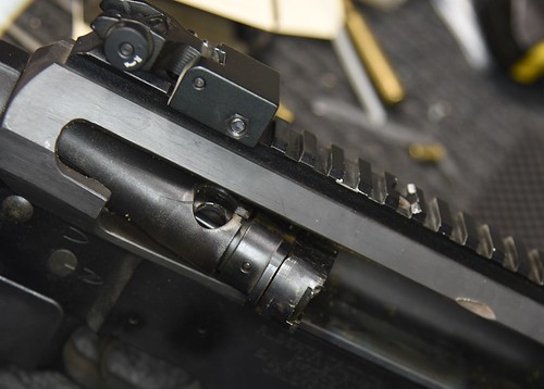 norinco da501 by Rod Henrickson, on Flickr norinco da501 by Rod Henrickson, on FlickrWhen I was a kid. I had the stick. I had the rock. And I had the mud puddle. I am as adept with them today, as I was back then. Lets see today's kids say that about their IPods, IPads and XBoxes in 45 years! Rod Henrickson | |||
|
| One of Us |
For those who don't know, the broken case extractor for 50 BMG is a 3/8-18 NPT tap. Simply put it into the dividing head and re-cut the shank to a common socket size with a carbide end mill. Then use an extension on a socket and screw it into the broken case and knock it out with an aluminum or brass rod. 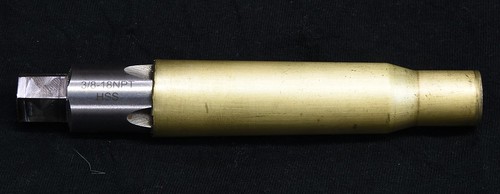 50 BMG case extractor by Rod Henrickson, on Flickr 50 BMG case extractor by Rod Henrickson, on FlickrWhen I was a kid. I had the stick. I had the rock. And I had the mud puddle. I am as adept with them today, as I was back then. Lets see today's kids say that about their IPods, IPads and XBoxes in 45 years! Rod Henrickson | |||
|
| One of Us |
The Remington 700 extractor is one of the most loved and one of the most hated, 2 cent devices that has ever been conceived. It is so tiny that it has the appearance that it would not support a postage stamp. To the gunsmith it is an ongoing source or aggravation and because of it's almost art form installation requirements, it is almost off limits to most hobbyists. All of the headaches aside, it is a sheering extractor and one of the strongest ever conceived. If a case gets stuck to the point of being irremovable, one of two things is going to happen. The extractor will rip a big chunk out of the rim, or the entire bolt nose will be ripped away. 99.9% of the time it is the rim that gives way. The major headaches with the extractor is firstly the cost. Despite their simple appearance they are expensive to make and they have a high, installation failure rate. The part itself is produced using a coining procedure which involves forming the part in complex dies. These dies do not last forever and have to be replaced periodically. Also, because the part is so small, there has also always been a problem with heat treatment. The end result is that the end product has always been in a state of continual dimensional flux and hardness. No two batches are the same in size, shape and hardness which makes for an ongoing battle of changes in the installation of them. Due to years of doing warranty for Remington I have seen them so soft they would simply crush. So hard they would shatter when you tried to collapse them on installation. So large that they would not fit under the rim and so small that they would flop around vertically like a fish in a shoe box. Another problem has always been diameters. Some too small, others too large. Back in the day, Remington issued a drawing with a series of bends and adjustments to be made which in their minds eliminated the diameter problems. While those dimensions and angles did work that week, they were totally useless when the next batch of extractors was run off. I won't even try to address the diameters and the bend angles. You sort of have to figure that out on your own and what works well with this batch of extractors generally goes out the window 3 months from now. There are however some common glitches that can be addressed during installation that will make them work better. The first is the height of the extractor, burrs and flatness. Many do come oversized and will be pinched in the bolt nose groove. Some are warped which causes the same problem and others have sharp burrs or hard edges which snag in the tooling marks on the bolt face and on the top of the inside of the groove cut. The new extractor should first be flattened, top and bottom and polished on a flat stone. I use a large flat 600 weight diamond hone. After that, all of the 90 degree angles should be slightly rounded with 400 wet and dry paper. I simply roll the paper into a tight joint and use it like a rat tailed file to break all of the sharp edges. The extractor is then slipped into place and tested to see that it slides round freely in the groove. If you can push it around with a common toothpick you should be fine. 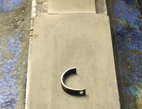 EXTRACTOR 6 by Rod Henrickson, on Flickr EXTRACTOR 6 by Rod Henrickson, on FlickrThe next problem to deal with is the hard closing or case rim sheering problem on closing. The 700 bolt should close on a cartridge with little to almost no force. If the bolt begins to close and then suddenly stops and requires more then finger pressure to close, then it is probably being caught on the top flat or shelf on the extractor and the rim has to forcibly push it aside or allow a chunk of itself to be cut away on closing to allow the extractor to slip under the rim of the bolt nose. The fix is to round or angle 2/3rds of the top flat (excepting about 1/32nd of an inch where the rivet is located). This rounded or angled edge will allow the case rim to push the extractor under the lip before the rim begins to engage the claw of the extractor. I use small stones in my Fordom tool to accomplish this and polish it after with rubber grit wheels. Care must be taken to not remove any material from the extractor claws purchase. I used to hold the extractors any manor of ways 25 years ago which led to a lot of launched and lost extractors and burned fingers. I finally built the small tool to hold them. It is nothing more than a lip turned into a piece of aluminum with a very powerful rare earth magnet pressed inside and a half a dime to keep the extractor from spinning in the tool. (When not in use, I keep the tool locked in an alarmed safe with a string tied to it to the trigger of a shotgun hidden inside in case some fool tries to steel it) The use of the tool is pretty explanatory from the picture and a monkey can make the tool. 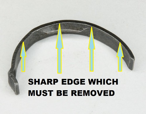 EXTRACTOR 2 by Rod Henrickson, on Flickr EXTRACTOR 2 by Rod Henrickson, on Flickr EXTRACTOR TOOL by Rod Henrickson, on Flickr EXTRACTOR TOOL by Rod Henrickson, on Flickr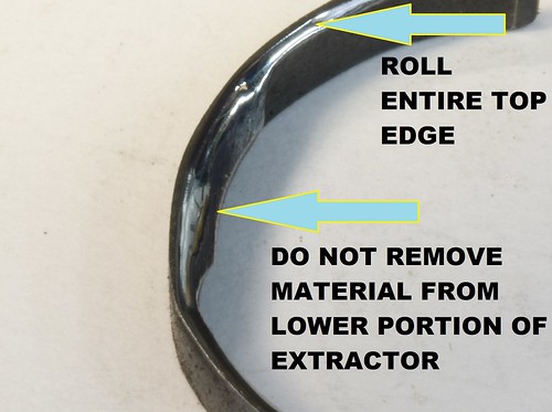 EXTRACTOR 1 by Rod Henrickson, on Flickr EXTRACTOR 1 by Rod Henrickson, on FlickrOnce the top edge has been cleaned up the extractor has to be pressed into the bolt lip and a punch is used to press the rivet area in place to see if the extractor purchase is going to be correct. At that point the extractor has to be carefully widened, closed or angled so that the claw will be fully exposed after riveting. Once it looks right the rivet is inserted and placed on the anvil and riveted into place. There are a million different anvils on the market and I have bought, made and used all of them. The best one I have ever used is this one that I made 20 years ago out of an old punch from a rough sketch someone gave me. This was made before the days of carbide and the tool was made with nothing more than a couple of chainsaw files and a dozen or so hack saw blades. It's not pretty but it has stood up to hundreds of extractor installs. It has 2 novel features. The hook allows it to nest up against the ejector so that you always know exactly where the anvil is in relation to the rivet. Because you know where it is you can also rotate the bolt slightly to allow you to flatten more on the inside or the outside of the rivet. Working on the outside of the rivet will tip the extractor outward and give you more purchase on the case rim. Working on the inside will tip the extractor inside of the recess and give less purchases. 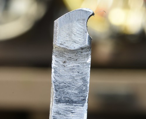 ANVIL 1 by Rod Henrickson, on Flickr ANVIL 1 by Rod Henrickson, on Flickr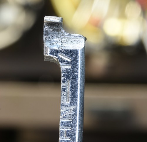 ANVIL 2 by Rod Henrickson, on Flickr ANVIL 2 by Rod Henrickson, on Flickr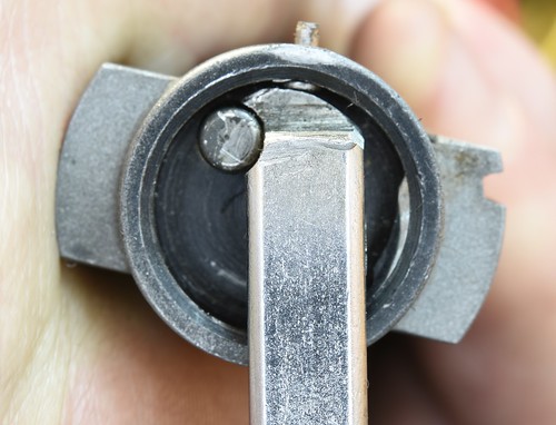 ANVIL 3 by Rod Henrickson, on Flickr ANVIL 3 by Rod Henrickson, on FlickrAfter the extractor has been riveted in the rivet must be cleaned up. I just do the outside with a small file and then lightly buff it and cold blue it. The next part is where most people screw up. The rivet head itself must also often be dressed off. Failure to do this will result in the rivet head pushing the case against the opposing side of the bolt rim and cause hard closing and case rim cutting on the rivet and the opposing side of the bolt nose. The rivet is simply dressed off using a small burr or stone until it no longer protrudes. If you have done everything right. You should be able to remove the firing pin array and the ejector and the bolt should close on a factory round with little more than slight finger pressure. If it doesn't, well then you fucked something up. Start again! 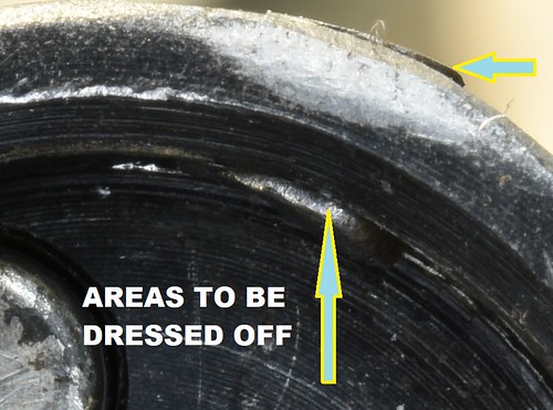 EXTRACTOR 3 by Rod Henrickson, on Flickr EXTRACTOR 3 by Rod Henrickson, on Flickr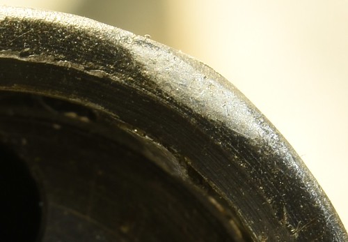 EXTRACTOR 4 by Rod Henrickson, on Flickr EXTRACTOR 4 by Rod Henrickson, on Flickr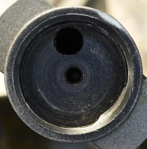 EXTRACTOR 5 by Rod Henrickson, on Flickr EXTRACTOR 5 by Rod Henrickson, on FlickrWhen I was a kid. I had the stick. I had the rock. And I had the mud puddle. I am as adept with them today, as I was back then. Lets see today's kids say that about their IPods, IPads and XBoxes in 45 years! Rod Henrickson | |||
|
| One of Us |
My greatest achievement and contribution to the gunsmithing fraternity has to be my Shotgun Bore Polisher. As if I invented the: "Redneck Boring Bar." Its nothing more than a 1/2 inch piece of aluminum rod, with a 1/8th inch slot cut in it and drilled and tapped on the end to allow it to be screwed on to 40 inches of 3/8ths aluminum rod. All you do is cut a chunk of your favorite 3M Scotch-Brite pad and jam it into the slot. (I like the taste of the red stuff bestestest) Then dip it in kerosene or whatever your favorite cleaning solvent happens to be and run it up and down the bore a couple of times with a cordless drill. It only takes 2 to 6 complete passes to rip out every last shred of lead and plastic out of the bore and chamber. The little black doohicky is simply a snap cap with a 3/8ths hole drilled in it to slide into the chamber to take the whip out of the rod when you wind up the drill. I have a box full of old Lewis Lead Removers and Brownells Flex Hones and they don't hold a candle to this for speed. On top of that the Scotch-Brite removes no material and barely scuffs the bluing inside the bore. I have been using the same one for 20 years or more. Barring a few times the handle was cut up to make some fool thing or another when the metal shop was closed. 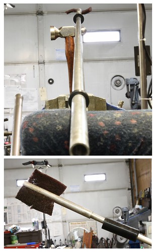 shotgun barrel polisher by Rod Henrickson, on Flickr shotgun barrel polisher by Rod Henrickson, on FlickrWhen I was a kid. I had the stick. I had the rock. And I had the mud puddle. I am as adept with them today, as I was back then. Lets see today's kids say that about their IPods, IPads and XBoxes in 45 years! Rod Henrickson | |||
|
| One of Us |
It's a foregone conclusion that math is not taught in European schools. I have always held on to the notion that the metric system was created to try to simplify math enough that people in Europe could navigate and use weights and measures well enough to drive to the store to get the needed supplies and make a cake. Obviously that notion failed miserably and the proof of that can be seen when the Europeans took the established measurements of rifle cartridges and tried to convert them to metric and re-manufacture those cartridges and the rifles that use them. The end result is that the European guns and cartridges are no where even close to what the original drawings called for and ultimately created the Delta ΔL problem that we are all so familiar with today. There are of course several lists on the internet of the differences in the delta measurement between the European and original American drawings. But, the world as it is today, they are all in metric so I have found that I am forever converting them to Imperial measurements for use in the shop. I normally keep a converted list stuck to one of the safe doors to refer to, but after a couple years they get ragged and dirty and I have to print off a new set which means trying to find a file I haven't refereed to in 2 years. So, I'll post it here for anyone who feels the need to have them. Cartridge ------------------------------- MM ---- Inch .17 Libra -------------------------- 0.250 ---- 0.0098 .17 Remington ---------------------- 0.07 ---- 0.0028 .220 Swift ------------------------- 0.1 ---- 0.0039 .221 Remington Fireball ------------ 0.09 ---- 0.0035 .222 Remington --------------------- 0.07 ---- 0.0028 .222 Remington Magnum -------------- 0.09 ---- 0.0035 .22-250 Remington ------------------ 0.08 ---- 0.0031 .223 Remington --------------------- 0.07 ---- 0.0028 .223 Winchester Super Short Magnum - 0.08 ---- 0.0031 .243 Winchester -------------------- 0.1 ---- 0.0039 .243 Winchester Super Short Magnum - 0.08 ---- 0.0031 .25-06 Remington ------------------- 0.15 ---- 0.0059 .257 Roberts ----------------------- 0.15 ---- 0.0059 .260 Remington --------------------- 0.1 ---- 0.0039 .270 Winchester -------------------- 0.15 ---- 0.0059 .270 Winchester Short Magnum ------- 0.1 ---- 0.0039 .280 Remington --------------------- 0.14 ---- 0.0055 .284 Winchester -------------------- 0.1 ---- 0.0039 .300 Lapua Magnum ------------------ 0.07 ---- 0.0028 .300 Remington Ultra Magnum -------- 0.11 ---- 0.0043 .300 Winchester Short Magnum ------- 0.1 ---- 0.0039 .30-06 Court Cartry ---------------- 0.16 ---- 0.0063 .30-06 Springfield ----------------- 0.16 ---- 0.0063 .308 EH ---------------------------- 0.1 ---- 0.0039 .308 Winchester -------------------- 0.1 ---- 0.0039 .325 Winchester Short Magnum ------- 0.11 ---- 0.0043 .338 Lapua Magnum ------------------ 0.05 ---- 0.0020 .338 Remington Ultra Magnum -------- 0.12 ---- 0.0047 .35 Remington ---------------------- 0.13 ---- 0.0051 .35 Whelen ------------------------- 0.15 ---- 0.0059 .358 Winchester -------------------- 0.1 ---- 0.0039 .375 Remington Ultra Magnum -------- 0.1 ---- 0.0039 .50 Browning ----------------------- 0.28 ---- 0.0110 5.45 x 18 -------------------------- 0.19 ---- 0.0075 5.45 x 39 -------------------------- 0.13 ---- 0.0051 5.6 x 39 --------------------------- 0.06 ---- 0.0024 5.7 x 28 --------------------------- 0.08 ---- 0.0031 6 mm BR Norma ---------------------- 0.07 ---- 0.0028 6 mm BR Remington ------------------ 0.07 ---- 0.0028 6 mm Remington (.244 Rem) ---------- 0.1 ---- 0.0039 6 x 47 SM -------------------------- 0.08 ---- 0.0031 6 x 62 Freres ---------------------- 0.12 ---- 0.0047 6.5 x 55 SE ------------------------ 0.09 ---- 0.0035 6.5 x 64 Brenneke ------------------ 0.19 ---- 0.0075 7 mm BR Remington ------------------ 0.08 ---- 0.0031 7 mm Express Remington ------------- 0.14 ---- 0.0055 7 mm Remington Ultra Magnum -------- 0.1 ---- 0.0039 7 mm Winchester Short Magnum ------- 0.1 ---- 0.0039 7 mm-08 Remington ------------------ 0.1 ---- 0.0039 7 x 33 SAKO ------------------------ 0.09 ---- 0.0035 7.21 Firebird ---------------------- 0.05 ---- 0.0020 7.62 x 39 -------------------------- 0.21 ---- 0.0083 7.65 x 53 Argentine ---------------- 0.18 ---- 0.0071 7.82 Warbird ----------------------- 0.05 ---- 0.0020 When I was a kid. I had the stick. I had the rock. And I had the mud puddle. I am as adept with them today, as I was back then. Lets see today's kids say that about their IPods, IPads and XBoxes in 45 years! Rod Henrickson | |||
|
| One of Us |
This is the second scope base I have had to make for the BRNO 803,7 double rifle. Well not scope base, as I don't think that the 2 screws would hold a full size scope, but a base for a red dot sight. There were some problems bastardizing this together. The first being is that the only base with the proper radius of 1.125 inch is the Weaver #74, which is made for the Savage 24V ONLY which of course is a gun that has been orphaned for many years. So getting the raw base can be tough. The other tough part is the screws. They are M4x.7. Very common in Philips or Robertson head if you want pot metal screws for holding your toaster together. Nearly impossible to get in Fillister slotted, cap screws or Weaver style oval head in good quality steel screws. What I finally ended up having to do was re-thread Weaver 8x40 screws. (As opposed to making them from scratch) You can try the die that came with your Irwin Toy, tap & die Happy Meal set. But I think you will end up having to spend $50 on a good high speed steel die after the high carbon, 8x40 Weaver screws re-thread your play-doh-die to 8x40. The recoil lug is 6mm in diameter but I didn't bother to record the dimensions for the screw holes as the two that I have done so far were about .040 inch different in hole spacing from each other, which seems to be common with BRNO sometimes. It's best to measure up the barrel and get proper dimensions every time. Happily, the recoil lug has been in the exact center between the two holes on both of the ones I have done. Charge lots. Between the screws, finding the #74 Weaver base, machine time, you are going to have quite a bit of time invested. 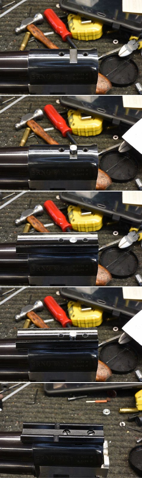 BRNO 803,7 by Rod Henrickson, on Flickr BRNO 803,7 by Rod Henrickson, on FlickrWhen I was a kid. I had the stick. I had the rock. And I had the mud puddle. I am as adept with them today, as I was back then. Lets see today's kids say that about their IPods, IPads and XBoxes in 45 years! Rod Henrickson | |||
|
| One of Us |
I was pulling my hair out looking for a thread size for a Lee Enfield and one of my Falcons directed me to a post on another forum where I found and ruthlessly stole this. Thx to the up-loader for this wee gem.  Smle bolt thread sizes 1 by Rod Henrickson, on Flickr Smle bolt thread sizes 1 by Rod Henrickson, on FlickrWhen I was a kid. I had the stick. I had the rock. And I had the mud puddle. I am as adept with them today, as I was back then. Lets see today's kids say that about their IPods, IPads and XBoxes in 45 years! Rod Henrickson | |||
|
| One of Us |
When I first bought these cheap, chicken shit little digital levels I didn't trust them to much. For the first few months I used to interrogate them and double check everything they told me with a spirit level. Now I just sick them to the bed of the machine, zero them and go to work. Now I trust them more than I trust the government and so far (two years) they have given me no reason to doubt them. The bottoms are magnetic and for stock work I simply stick them to a large parallel, set the whole works on the mill table and zero both. Once zeroed I just set them on the fore stock and twist the stock around in the vise until I'm within a couple of tenths. That is usually just as accurate as I can level things with a common spirit level. The nice thing is to be able to see X and Y at the same time, rather than twisting the spirit level back and forth. I also don't have to try to remember where the bubble actually sits on X and Y because the machine has walked around a bit with floor warp. Having water heated floors is the LAST thing you want in a machine shop. Fucking floor twists and heaves around like a pretzel ! 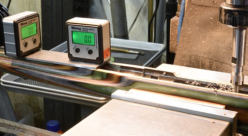 digital protractors by Rod Henrickson, on Flickr digital protractors by Rod Henrickson, on FlickrWhen I was a kid. I had the stick. I had the rock. And I had the mud puddle. I am as adept with them today, as I was back then. Lets see today's kids say that about their IPods, IPads and XBoxes in 45 years! Rod Henrickson | |||
|
| One of Us |
The Winchester 94 link problem is an ongoing problem that we have all been dealing with since we were baby gun plumbers. The following round is cammed forward by the tit on the link as the leaver is closed and eventually the tit wears out or breaks. The age old fix has always been to weld them up with tool steel and then recut them in the miller. Not a big job but it's expensive enough that a lot of guys would like a permanent fix. The Japanese did just that when they redesigned the 94 after the Belgians moved the production there. Their answer to the problem was a new link with a spring loaded, articulating shell stop that solved the problem. It's a rather expensive part, but once installed it's fixed, FOREVER! The new link is basically a drop in unit except that the leaver is a bit to wide for the slot in the link. You can file the slot bigger which looks a bit unsightly or file the leaver a bit which also looks a bit unprofessional. The simple, good looking method is to simply close the leaver tight, before you disassemble the gun and make a simple scribe mark on the right hand side of the leaver using the bottom of the receiver as a guide. Then, after the gun is disassembled lay the leaver on the mill table and clamp it with the scribe mark running parallel to the X or Y axis and remove what is needed right up to the scribe mark. It's quick, simple and looks good. You can cold blue it if you want. Best of all, it's a permanent fix. There is still a slight sticky area at the bottom of the stroke. But it generally wears in after working the leaver about 20 times. ADD NOTE: For clarification, I should have mentioned: You very seldom have to remove more than .003 inch. If you have done everything right the cut will all be inside the receiver and invisible when the leaver is fully closed. 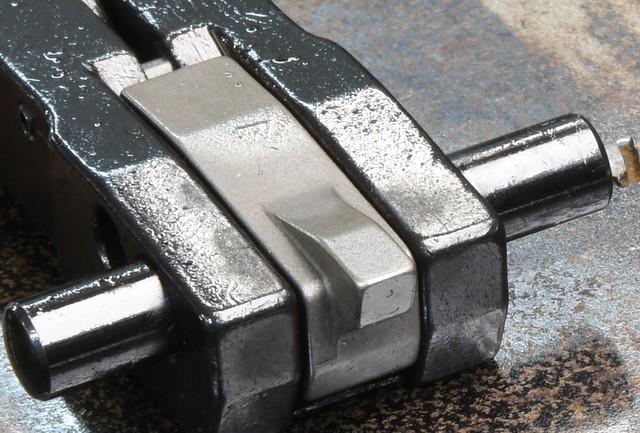 94 articulating link2 by Rod Henrickson, on Flickr 94 articulating link2 by Rod Henrickson, on Flickr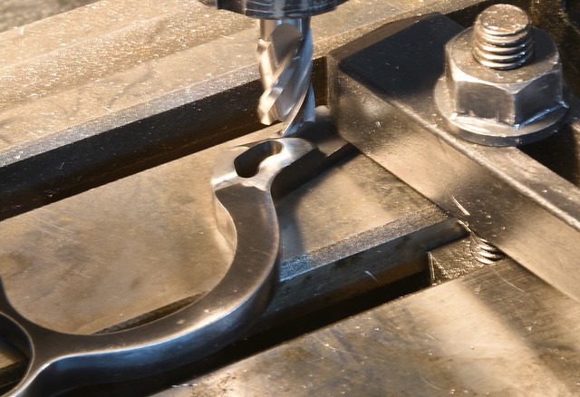 94 articulating link1 by Rod Henrickson, on Flickr 94 articulating link1 by Rod Henrickson, on FlickrWhen I was a kid. I had the stick. I had the rock. And I had the mud puddle. I am as adept with them today, as I was back then. Lets see today's kids say that about their IPods, IPads and XBoxes in 45 years! Rod Henrickson | |||
|
| One of Us |
If anyone is interested, I'm selling my 30 year old recoil pad clamp for gluing on pads. Going cheap, $5,000.00. Don't be silly. It's not really for sale! 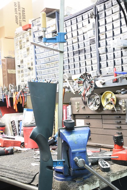 recoil pad clamp1 by Rod Henrickson, on Flickr recoil pad clamp1 by Rod Henrickson, on Flickr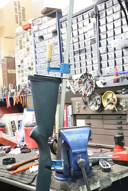 recoil pad clamp2 by Rod Henrickson, on Flickr recoil pad clamp2 by Rod Henrickson, on FlickrWhen I was a kid. I had the stick. I had the rock. And I had the mud puddle. I am as adept with them today, as I was back then. Lets see today's kids say that about their IPods, IPads and XBoxes in 45 years! Rod Henrickson | |||
|
| One of Us |
About a year ago the swing on my mill head decided to give up the ghost. I have had this happen on Bridgeport machines a few times over the years and the Hau Dong machines are just a clone of them so I had a pretty good idea what was fucked. In the Bridgeports it is usually either the worm adjustment shaft or key which has broke. Or the worm gear or the quill housing adjustment gear that fits into the millrite has sheered off a few teeth. The quill housing adjustment gear can usually just be flipped over to expose fresh teeth because no one ever swings the head upside down anyway. Just to be certain, I called my tool falcon in Last-Breath-Before-Death, Saskatchewan and ordered the whole damned works. For giggles and to show how simple it is to do yourself, I thought I would toss up a couple of pictures. The job itself is actually pretty simple and if you don't have some means to lift the head you will need a couple of strong backs because the head and motor complete weighs about 250 pounds. Being a one man shop, I swung the head over on the turret so that it was perched directly below the support beam of the catwalk in my shop and used a common, come-along to lift the head. I just ran a piece of 1/2 inch ready rod through the spindle with a chunk of angle aluminum on the top to hook into. Normally the heads will balance nicely if your hook is located just between the spindle and motor. After that, the 4 bolts for the swing adjustment are loosened and the head is raised until the pressure has been taken off of the bolts. Then the horizontal adjustment for the head is pulled back to free the head from the column. The next part gets a bit messy. The entire swing system and gears are generally swimming in grease from the 1930s which has been infiltrated by 70 or 80 years of cast iron dust which has been worn away from decades of swinging back and forth. This black, brackish concoction is easily removed from the machine with a few gallons of kerosene and a brush. You can generally get it off your hands with a small hatchet or meat saw, or you can simply wait 6 months for it to wear off. When I pulled mine apart I discovered that the whole works was BONE DRY, with a slight dust of rust. Apparently the little Chinese fellow in charge of grease that day either had the day off or needed some grease for his tractor or the family tuk-tuk and my grease went home with him in his lunch box. All of the parts were in otherwise, brand new looking in like new condition with no apparent wear. Everything had simply galled enough under the extreme pressure to stop movement and I hadn't forced anything so nothing was broken or distorted. After filling the entire cavity with good old, high pressure, farmer grease and bolting it back together the head now swings back and forth with one hand using a small, 6 inch, 1/4 inch drive socket. So, I greased up the new parts, put them in a plastic bag and wired them to the water pump inside the column for the guy who buys it after I die. For the most part, mills are pretty simple to repair. It's just finding ways to deal with the weight of the parts. A simple method of lifting the head on a Bridgeport style machine. The heads are really not very heavy and can be removed by a couple strong men. You could remove the motor if you wanted to strip the weight in half, but it's just a lot of extra work. 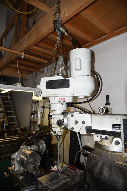 Pull Hau Dong Head2 by Rod Henrickson, on Flickr Pull Hau Dong Head2 by Rod Henrickson, on FlickrThe separated head with the new parts, which were not actually needed for this job, ready for installation. 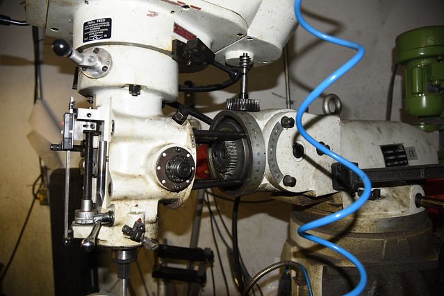 Pull Hau Dong Head by Rod Henrickson, on Flickr Pull Hau Dong Head by Rod Henrickson, on FlickrADD NOTE: If you look at the last picture, at the quill housing adjustment gear, you will notice that it is held on by two bolts in the picture. I'm almost 99% certain the Bridgeports, Laguns and Racers are the same. If you strip off a couple of teeth for some reason, it is not necessary to rush out and buy another gear. Simply flip the gear upside down and tighten the bolts back up. You will NEVER, turn the head so much to one side that you will encounter the broken teeth in normal use. When I was a kid. I had the stick. I had the rock. And I had the mud puddle. I am as adept with them today, as I was back then. Lets see today's kids say that about their IPods, IPads and XBoxes in 45 years! Rod Henrickson | |||
|
| One of Us |
Running out of 416 brakes so the "hotdog factory" is up and running again. It's hard to believe that this "can opener" machine was brand new just 4 years ago. You don't really consider how many hours you stand at a machine until you realize that the swarf has long since eaten through the paint on the splash guard and is starting to dig a hole into the steel and all of the paint on the apron where my thumb and fingers drag on the friction clutch is completely worn away. 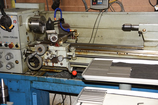 hotdog factory by Rod Henrickson, on Flickr hotdog factory by Rod Henrickson, on FlickrWhen I was a kid. I had the stick. I had the rock. And I had the mud puddle. I am as adept with them today, as I was back then. Lets see today's kids say that about their IPods, IPads and XBoxes in 45 years! Rod Henrickson | |||
|
| One of Us |
I had to replace another Auto 5 Action Spring Tube. It's one of those jobs I hate because it generally ruins almost a full day, but I have been doing them since my days of doing Browning warranty and I'm to dumb to stop. What you want to happen is, you want to heat the tang and whats left of the broken off tube up and just have it fall out under gravity. Or knock it out with a punch after you get the brazing hot enough to let go. Of course, in the real world that very seldom happens. Having tried that and stopping before you fuck something up it's time to surrender and move to the milling machine. In the bad old days we used everything from dremel tools, chucking reamers, drills to hammers and chisels to get out the broken tube. I can assure you that all of these methods take a lot more time than the mill and often lead to DISASTER ! You can't afford to buy customers to many Auto 5 receivers so it's best to just do it the proper way and be done with it. If you have a horizontal mill, you're golden. Clamp the tail of the receiver in the vise and install a close fitting pin all the way down and level and square it to the machine. Then lock a 1/2 inch carbide end mill into the horizontal spindle and drive it straight in .700 inches from the start of he tang. If you have only a vertical machine you will have to first remove mag tube. The safest way to accomplish this without damage is to remove the magazine cut off screw as it serves to lock the mag tube and then grasp the mag tube in an ER40 collet and screw the receiver off. Be forewarned that 5C collets will bite and crimp the tube and chucks will generally crush or mark them. The only 100% safe way I have found is the ER collets. 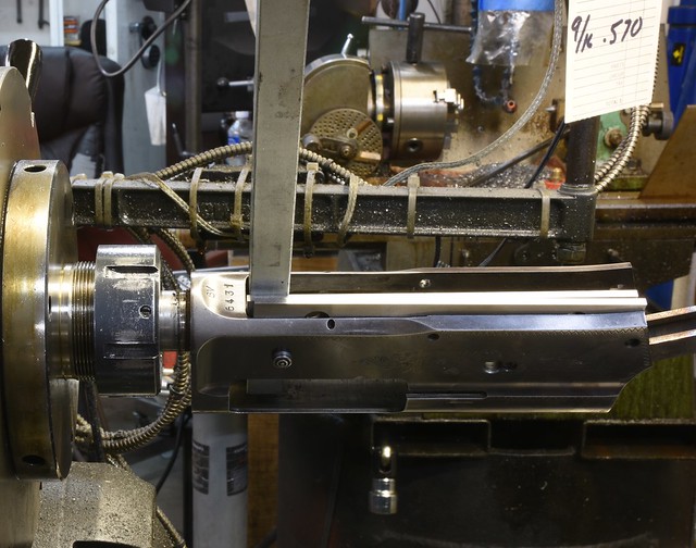 auto51 by Rod Henrickson, on Flickr auto51 by Rod Henrickson, on FlickrAfter getting the tube off it's a simple matter of clamping it to an angle plate and running a close fitting pin down and squaring the pin up to the mill. You will probably need some sort of spacer as the side of the receive is not flat. I use a parallel with masking tape to protect the finish on the gun. A simple toe clamp is used to hold the receiver to the angle plate. Be careful not to over tighten it and crush the inside rails on the receiver. 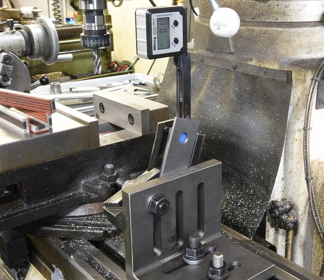 auto52 by Rod Henrickson, on Flickr auto52 by Rod Henrickson, on Flickr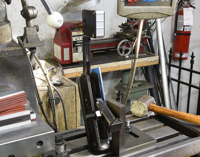 auto53 by Rod Henrickson, on Flickr auto53 by Rod Henrickson, on FlickrAfter that it is a simple matter of finding the centre of the old tube with an edge finder and driving a 1/2 inch carbide end mill straight down .700 inch from the rearmost portion of the tang. You will have to drive the mill slowly at about 600 RPM with lots of oil to brake chatter generated by the sides of the flutes. Take your time. If you haven't already seen it, setups and milling like this can be an invitation for disaster! After milling out the old tube its a simple matter of clamping the receiver in a vise and levelling the tang using a pin so that gravity and the capillary action of the silver solder will centre the tube in the hole. 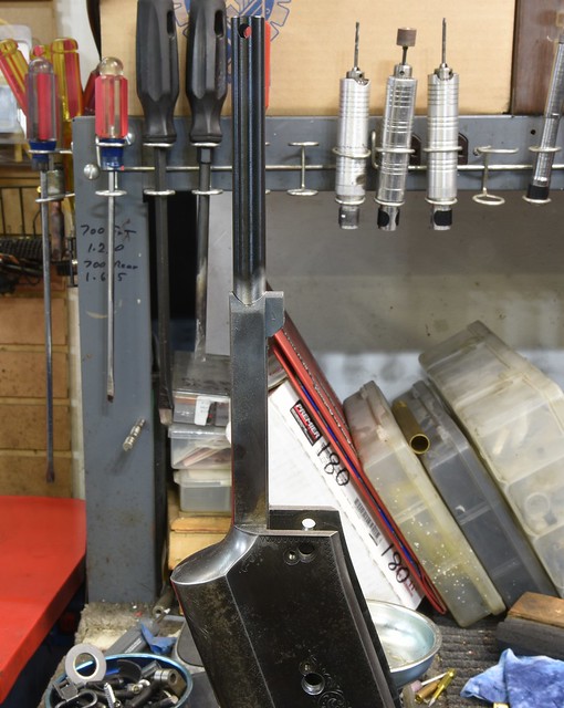 auto54 by Rod Henrickson, on Flickr auto54 by Rod Henrickson, on FlickrDe-grease with lacquer thinner and apply high temp flux to the hole and the new tube and slide the tube in and heat the tang with a MAP or acetylene torch. When the flux goes clear start feeding the low temp silver into the joint with heat all around the perimeter. The solder should pull the tube straight if you have done everything right. Do a visual check and let the solder set and put your level on it to double check everything. 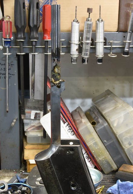 auto55 by Rod Henrickson, on Flickr auto55 by Rod Henrickson, on FlickrIf everything is correct knock the flux off with a wire wheel and try it in the stock just to double check everything. 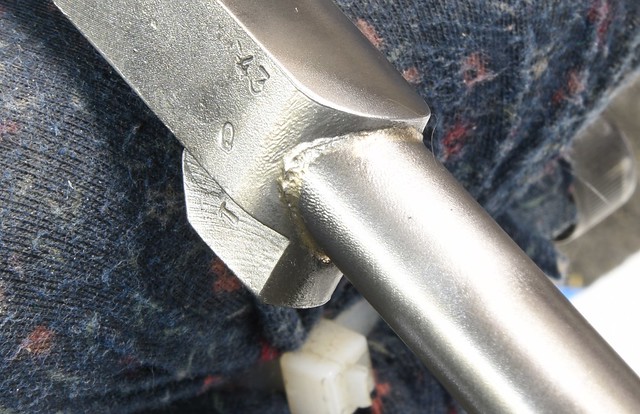 auto57 by Rod Henrickson, on Flickr auto57 by Rod Henrickson, on FlickrOnce you are sure that everything is going to work, run a 13/32nd chucking reamer down the tube to clear out any excess solder and flux and polish the rest out with a piece of aluminum rod with 320 paper until everything is smooth and the follower travels up and down freely. The final step is to drill through the new tube through the stock bolt hole using the mill and run a 1/4x40 tap down to cut out any excessive solder and thread the new tube. Try not to laugh to hard. I made that simple gun tap about 15 years ago when I was pressed for time with the intent of buying a custom tap when that one finally gave out. Well, 15 or 20 receivers later it has steadfastly refused to die, so I guess it's earned it's existence and I've kept using it. 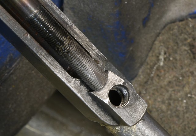 auto56 by Rod Henrickson, on Flickr auto56 by Rod Henrickson, on FlickrWhen I was a kid. I had the stick. I had the rock. And I had the mud puddle. I am as adept with them today, as I was back then. Lets see today's kids say that about their IPods, IPads and XBoxes in 45 years! Rod Henrickson | |||
|
| new member |
Keep your plow and sword, know how to use both. | |||
|
| One of Us |
I'm not sure about people in the USA, but up here we get an awful lot of SKS scope mounts to do. There are several types of mounts. None are really great. The most popular one here is the little cast job and I think that people are outwardly attracted to them because of the price. Until they go to install them. Some get out there files and try to install them that way and invariably they take a couple of thousandths of an inch to much and then they simply flop around and they cant hold zero. Ive seen a lot of innovative fixes to this. Some guys put in shims on the noses, Some weld the noses up and try again. The most creative one to date was one the guy simply buzzed the base on with his arc welder. That one was great until the firing pin broke and we had to cut it apart to put a new one in. Back when I first started doing them I followed the instructions and quickly learned that filing was not the best way to approach it. You only buy so many for your customers before you start looking for a better way. The first thing that you have to understand is that they are rough castings and are twisted up like a pair of mating snakes. If you don't square the base to the bottom you are going to end up shimming the base which is screwed to the top, to get it to bore sight. Also the cover won't sit flat on the rifle and it will rock if you don't flatten it. I didn't show a picture of the setup for this but it's very simple. You simply drop it in the mill vise with the base flat on the bottom of the vise and tighten the vise and take a skim off of the area that contacts the receiver. 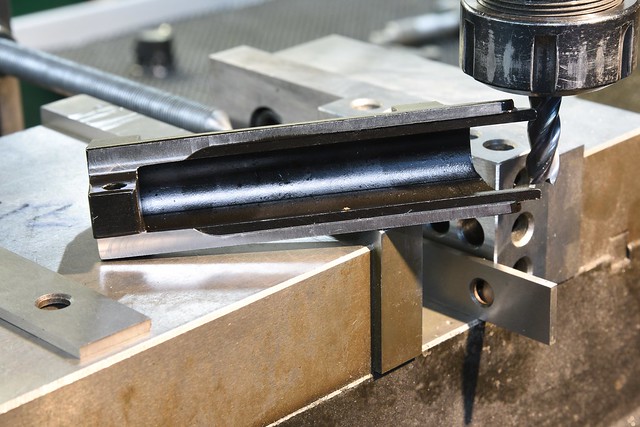 SKS Scope Mount 1 by Rod Henrickson, on Flickr SKS Scope Mount 1 by Rod Henrickson, on FlickrAfter that, the tabs at the front have to be milled so that they will just slide into the ways of the receiver with solid pressure. As per the photo I set it on a parallel and use a 1x2 to get clearance from the tab in the back that the assembly pin goes into. I also use a material stop so that I can take it out and put it back in and have it come back to the same spot. I find the low tab by checking it with the Z axis, determine if I have enough material to play with (You usually have TONS) and then flip the base over and cut the high tab down so it is equal to the low tab. I then try it in the gun and take some measurements, cutting a few thousandths off of one and then flipping the base over and cutting the same off the other. I do this until the tabs will just slip into the rails with heavy pressure. I don't hammer them in as some do as it simply bends one of the tabs and you will end up with your base pointing way to the right or left. That mistake can be adjusted out when you install the top part of the base but it looks unsightly having the dust cover part sitting to one side or the other. Plus, if you get it too crooked the bolt will drag on the dust cover and impair the function. 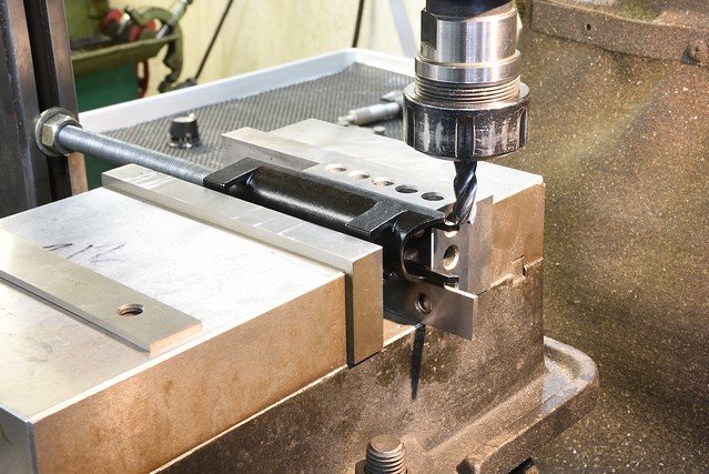 SKS Scope Mount 2 by Rod Henrickson, on Flickr SKS Scope Mount 2 by Rod Henrickson, on FlickrOnce the first two steps are complete its time to set the depth of the two lugs so that you can get the assembly pin to go through. I set the dust cover on two parallels in the vise and use a material stop so that I can take it out and put it back in repeatedly. The angles on the noses are at 45 degrees so I use a 90 degree cutter to take a few thousandths off at a time. As it gets close, I start trying to tap the assembly pin through with a 2 ounce hammer and reduce my cuts to .003 inch or less until I can just nicely drive the pin through without really going berserk on it. The pin should build up a substantial amount of forward pressure on the cover and this will keep the cover from moving around and changing the POI. Done correctly this system does work rather well as long as the customer is not continuously taking it apart and putting it together and wearing down the surfaces. The mill does take most of the headache out of this installation and I have never gone to far and had to buy a customer another base since I started doing it this way. I do have a spare one on hand mind you. Just in case. Never say never ! If you find that you have cut so much that you can force the assembly pin through with your hand or thumb, you've gone to far. Weld it up and re-cut it or grab a new base and start over. A hammer must be used to assemble it and a hammer and punch must be used to disassemble it or you won't have enough forward force to keep everything tight. 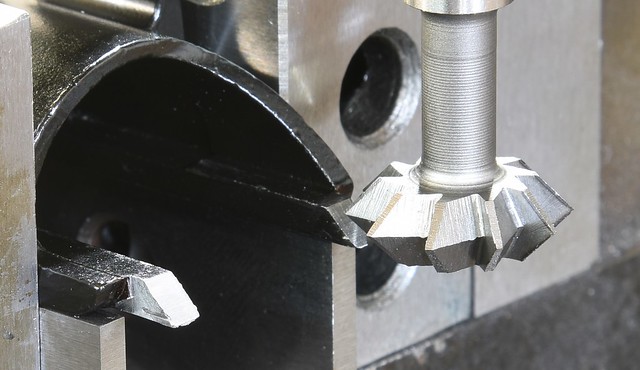 SKS Scope Mount 3 by Rod Henrickson, on Flickr SKS Scope Mount 3 by Rod Henrickson, on FlickrWhen I was a kid. I had the stick. I had the rock. And I had the mud puddle. I am as adept with them today, as I was back then. Lets see today's kids say that about their IPods, IPads and XBoxes in 45 years! Rod Henrickson | |||
|
| One of Us |
Geometry for 98 Mauser bolt shroud threads. Well, this one at least. 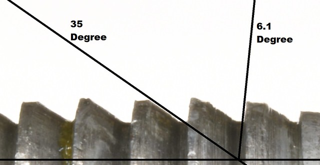 98 Mauser Buttress Thread by Rod Henrickson, on Flickr 98 Mauser Buttress Thread by Rod Henrickson, on FlickrWhen I was a kid. I had the stick. I had the rock. And I had the mud puddle. I am as adept with them today, as I was back then. Lets see today's kids say that about their IPods, IPads and XBoxes in 45 years! Rod Henrickson | |||
|
| One of Us |
M6 tap, or a long bolt, works for various 22 cases that had the head come off. | |||
|
| One of Us |
The classic trick for 22 RF with separated heads is to push a 22 caliber cleaning rod down the barrel and through the receiver. Then screw on a 30 caliber brass brush and pull it into the case so that it is flush with the barrel face. The bristles will all bend rearward as you pull it in. Then tap on the handle of the cleaning rod with a small hammer and the bristles will catch on the case mouth and push it out. Works 99% of the time with no risk of chamber damage. You can also play a propane torch into the chamber before doing it and it will melt any of the old lube that may be holding the case in. When I was a kid. I had the stick. I had the rock. And I had the mud puddle. I am as adept with them today, as I was back then. Lets see today's kids say that about their IPods, IPads and XBoxes in 45 years! Rod Henrickson | |||
|
| One of Us |
So, I had an interesting one today. One of my customers came in with a screw driver poke hole, completely through the palm of his hand. This is not a new thing to me, but most of the time the guys don't shove them completely through. The downside is that he wouldn't let me take a picture of his hand. It's pretty groddy! It seems he was trying to remove the extractor from his Marlin 336 by following a video that a kid had posted on line and things sort of got out of hand. I watched the video with him and I can see how he would have stabbed himself. I'm surprised the kid on the video didn't do it too. So I decided to do a short video on how to remove and install them. https://youtu.be/-kTD0kNS0Qo When I was a kid. I had the stick. I had the rock. And I had the mud puddle. I am as adept with them today, as I was back then. Lets see today's kids say that about their IPods, IPads and XBoxes in 45 years! Rod Henrickson | |||
|
| One of Us |
Over the years I have seen probably 15 or 20, BL22 Locking Blocks that were improperly installed. Many to tight, which gave hard close, or failure to close. Also many that were over fit which gave buggy case heads and or leaver snap on firing. Leaver snap is the most common because people attack the block with a file and over fit them. On firing, the breach bolt will travel rearward to take up the excess headspace created by the over fit block and that rearward movement is transferred to the leaver which gives a slight sting or tap to the fingers on firing. I have had more than one guy say that he got a small electric shock when firing the gun and I suppose that it does feel sort of like that. The first step in fitting them is to round the edge designated by the yellow arrow with the (R) in the picture. It is a very slight radius. No more than 1/64 of an inch. Tiny in fact. Then try the block in the gun. If it closes fully and test fires fine you're good to go. If not, then you have to create a bit of a draft on the back side to allow it to close. Generally it is NEVER more than .004 inch at the start of the draft. The blocks generally will measure.444 inch from new. To cut the draft set your sine bar to 1.5 degrees and take a .001 cut across it. The cut should never exceed beyond the length of the extended portion on the Locking Block as shown between the 2 yellow arrows. If your draft gets to long the block will bind on closing. After rounding the edge and taking the first .001 inch, try the block in the gun again. Often this is enough to allow the action to fully close and the trigger to engage and fire. If not keep cutting .001 at a time until everything works. If you get to the point where the draft is at it's maximum length, add a bit more to your sine bar to bring the angle to 2 degrees. I have never had to angle the sine bar more than 2 degrees and I have never had to remove more than .004 from the start of the angle. If you go to far and you begin to get headspace, case head bugging or leaver snap. Start over with a fresh block. Don't try to weld and reclaim them. They will warp and crack. The blocks are only $10 for a new one but don't toss away the over fit block. Sooner or later you will run across a gun it will fit. 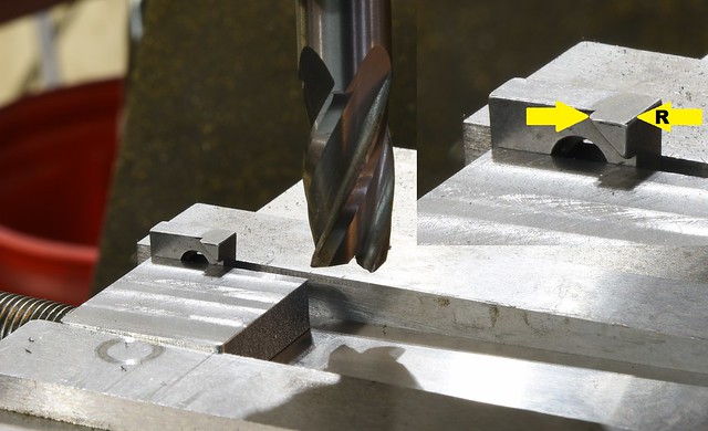 BL22 Locking Block by Rod Henrickson, on Flickr BL22 Locking Block by Rod Henrickson, on FlickrWhen I was a kid. I had the stick. I had the rock. And I had the mud puddle. I am as adept with them today, as I was back then. Lets see today's kids say that about their IPods, IPads and XBoxes in 45 years! Rod Henrickson | |||
|
| One of Us |
The BSA bolt disassembly tool for the un-drilled cocking piece models. Over rotate the bolt, snap it on and unscrew the fire array. Not so much easy if you don't have the tool. 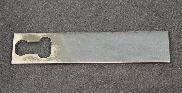 BSA bolt tool 1 by Rod Henrickson, on Flickr BSA bolt tool 1 by Rod Henrickson, on Flickr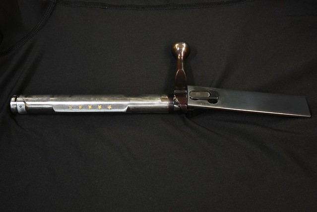 BSA bolt tool 2 by Rod Henrickson, on Flickr BSA bolt tool 2 by Rod Henrickson, on Flickr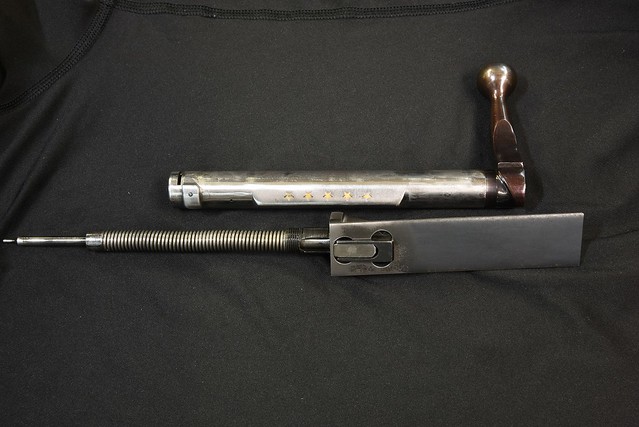 BSA bolt tool 3 by Rod Henrickson, on Flickr BSA bolt tool 3 by Rod Henrickson, on FlickrWhen I was a kid. I had the stick. I had the rock. And I had the mud puddle. I am as adept with them today, as I was back then. Lets see today's kids say that about their IPods, IPads and XBoxes in 45 years! Rod Henrickson | |||
|
| One of Us |
One of my competitors was in not so long ago and slyly asked how I was threading Remington 597s, because there is no room in the headstock for the barrel lug. I said: "Well you could hold them against a face plate on a center and dog it off. Or hold them in a 4 jaw and dial them in!" Then I leaned foreword and whispered: "But I cheat. I hold them in ER40 collets to save time!" I could tell from his (BOVINE STARE), that he didn't have a clue. But he nodded his head and said: "OOHHHHhhh, so THAT'S, how you do it!" I didn't exactly lie. I just omitted a couple of things. Some days you have to make your own entertainment. 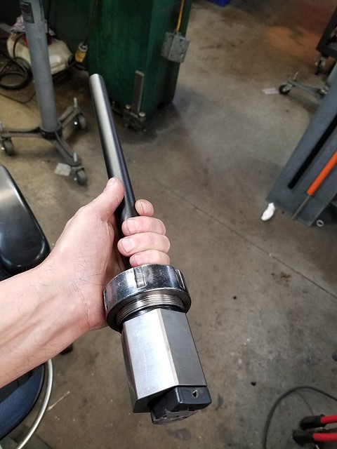 Remington 597 1 by Rod Henrickson, on Flickr Remington 597 1 by Rod Henrickson, on Flickr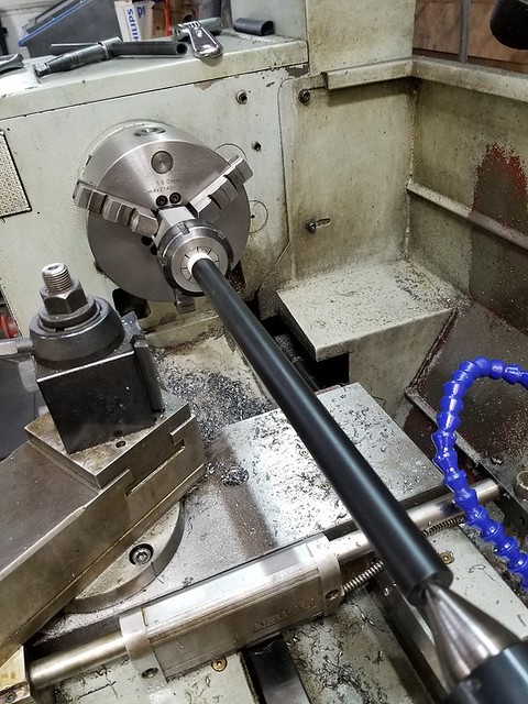 Remington 597 2 by Rod Henrickson, on Flickr Remington 597 2 by Rod Henrickson, on FlickrWhen I was a kid. I had the stick. I had the rock. And I had the mud puddle. I am as adept with them today, as I was back then. Lets see today's kids say that about their IPods, IPads and XBoxes in 45 years! Rod Henrickson | |||
|
| Moderator |
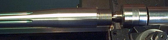
Carl Gustav 1900 barrel thread
#dumptrump opinions vary band of bubbas and STC hunting Club Information on Ammoguide about the416AR, 458AR, 470AR, 500AR What is an AR round? Case Drawings 416-458-470AR and 500AR. 476AR, http://www.weaponsmith.com | |||
|
| One of Us |
Tag for good info... | |||
|
| Powered by Social Strata | Page 1 2 3 4 5 6 |
| Please Wait. Your request is being processed... |
Guns, Politics, Gunsmithing & Reloading Gunsmithing

Visit our on-line store for AR Memorabilia
