 Guns, Politics, Gunsmithing & Reloading Gunsmithing
 Go | New | Find | Notify | Tools | Reply |
| Large ring ground to small ring mauser | Login/Join |
| One of Us |
This 72 year old kid has recently been enamored with Carcano's. I see beauty in them: http://castboolits.gunloads.co...-A-Couple-of-Hybrids | |||
|
| One of Us |
I dunno, but I am thinking we can at least make 4 pages posting about anything but the topic starter of..... Im looking at a DWM mauser that has been ground to small ring dimensions, unknown who did the work. I have never owned one, anything to look out for? We have brought in, LR that weren't ground to SR and torture tested, Grisel's SR that wasn't a LR ground to SR, LRs that weren't ground, SR that weren't ground and had a small shank, Winchester, Enfield and some others that weren't LR, SR or ground, pics of a SR rifle that wasn't ground, SR 96s that weren't ground but were torture tested and now Carcarnos. So there is plenty of things that have nothing to do with grinding a LR into a SR and "anything to look out for" that we haven't tossed into this thread yet. So the sky is the limit! | |||
|
| one of us |
I took the Turk down to 1.290 today; leaving the reinforce over the right side race way as on a Springfield. Looks pretty good. At least it looks pretty good for such an ugly action to start. So, the receiver ring is done and rough polished. I'll do the bridge later and see if I can find some bottom metal that isn't too pitted. When it is good enough to be covered by the shop motto (Gunsmithing by Leeper; it won't make ya puke), I'll figure a way to post a picture. The bolt is pretty ugly but might clean up OK. I will NOT try to blow it up. Regards, Bill | |||
|
| One of Us |
Bill were you able to measure that relief cut diameter, ignoring the deeper secondary cut at the extractor? | |||
|
| one of us |
Yes I was. Ignoring the cut at the extractor, the diameter of the relief appears to be about 1.013" At the extractor cut, it measures 1.049 which gives a depth of about 36 thou, which is what it looks like. The reinforce left above the raceway maintains wall thickness all around. I made the reinforce with a 1/8 radius on both sides and front. Winchester should have done this on the Model 54 and Model 70. Regards, Bill. | |||
|
| one of us |
Bill, I am very visual, is it possible for you to post some pics showing what you are describing? BB | |||
|
| One of Us |
Ignoring the deeper cut at the extractor that makes the ground down Turk wall 0.120" thick. I have a dissected large ring/ large shank around here somewhere but I believe that relief cut is larger in diameter. It looked like richj's pic back in page 1. Will have to keep looking. I also have a threading barrel shank/lug abutment insert for one of the aluminum target receivers, I believe it is a Kelby. It's wall thickness is only 0.105", but of course modern steel and heat treatment. | |||
|
| one of us |
I've been threatening to figure out how to post some pics for years now. I'll give it a shot. I think it will have to include some help from my wife and her cell phone. I know of some really stupid people who can post pics so I, easily as smart as the average chimp, should be able to do it. I won't be finishing the work on the receiver for a couple of days. While I have the rotary fixture set up on the mill, I have to make some muzzle brakes. When I'm through with those, I'll get back to the Turk. Regards, Bill | |||
|
| one of us |
OK, I will wade into this mess. I have a 1916 Erfurt receiver that I will cut up to measure the inner recess's Have as well several 24/30 FN front receiver rings that I can cut up as well. That way I can have a friend who has both RC and B scale testing machines to get a true hardness on areas inside the front ring FYI, years ago I cut down a 1935 Arg receiver made by FN into a small ring/large thread to build my wife a 257 Rbts. Once I had milled the front ring down the hardness of the ring area in the milled areas was RC 32 - 35, more than I suspected it would be. Have never had any issues with the rifle over the years Now for the icing on the cake, I have a 1948 Spanish large ring receiver, that my father re-barreled to 30-06 in the year 1976 for his nephew. My cousin brought the rifle in to me last year. Saying it simply is not shooting like it used to do and can we re-barrel it and make a longer barrel at the same time. I went to remove the barrel and OMG I could unscrew it by HAND So put the barrel back on and checked the head space as well. DANG, OMG. using the same gauges that my father had used in 1976, that receiver/barrel now has .007" to .008" headspace. The lugs are set back badly, but the front section of the receiver also streched. Did a quick RC test on it and WOW, its below RC 20, and we all know how hard it is to measure when they are that soft. Since it has all of the factory markings, the outside is still within their spec. They stamped the s/n on the left hand side of the receiver, and you can see inside in the raceway each stamp mark, Dang it is soft. I am swapping out the bad 1948 receiver for a good receiver, and also will section the bad receiver to take some measurements, and hardness of. Just a Turkey shoot, some actions are good, some much better, while others used a different method of machining/heat treating which then caused serious problems down the long road. Jim Wisner | |||
|
| One of Us |
Words from the wise! Wisdom doesn't come from reading internet posts or applying blanket statements over and over. It has to do with YEARS of intelligent experience on the subject matter. JWisner has it in spades. Those interested in having a rifle built on a 98 Mauser should have a trained, qualified, experienced, LICENSED gunmaker/gunsmith in the appropriate field perform the work. Relying on an internet forum filled with strong opinions doesn't build a safe functional custom rifle. I'm not at all saying there isn't a vast amount of great information available here and on other forums. You just have to have a pretty good working background in the subject matter to wade through all the BS that comes floating by. | |||
|
| One of Us |
Again...elasticity is the limiting factor..stressed beyond it's limits to return to original dimension. | |||
|
| One of Us |
Please do! I think it will be alarming how thin the wall would be on many LRs ground down to SR at the clearance cut. | |||
|
| One of Us |
This makes me want to buy a 28 buck inside digital caliper off Amazon. | |||
|
| One of Us |
Jim..thoughtful post..Tell me..how do you measure "stretch" | |||
|
| One of Us |
Let's put some real numbers out there. Wall thickness Wall @ extractor M-70 .207 .985 98 .206 .148 Sm ring lge thread .156 .998 Enfield .170 .162 If taking a lge ring/lge thread to small ring, BUT leave reinforcement as I suggested way back, the W.T. @ extractor would remain .148 Keep in mind these measurements are affected by thread pitch and "V" thread vs (almost) sq. thread on the Enfield. The pressure is largely contained by the barrel anyway. Do I advocate the large thread modification to the 98? Certainly such a mod must be given serious thought and most likely heat treat. So...no comment! Just an attempt to temper the hysteria! | |||
|
| One of Us |
Jim, If you want, I have Rockwell C, Superficial 15N, 30N, 45N, and micro hardness testers. Mauser's specifications are given in 30kg (30N) and 150kg (Rockwell C). I have several cut up actions that I sectioned, analyzed, or sent out for analysis if you would like numbers for comparison. Nathaniel Myers Myers Arms LLC nathaniel@myersarms.com www.myersarms.com Follow us on Instagram and YouTube I buy Mauser actions, parts, micrometers, tools, calipers, etc. Specifically looking for pre-WWII Mauser tools. | |||
|
| One of Us |
Lets... not clog up the thread Nathaniel Myers Myers Arms LLC nathaniel@myersarms.com www.myersarms.com Follow us on Instagram and YouTube I buy Mauser actions, parts, micrometers, tools, calipers, etc. Specifically looking for pre-WWII Mauser tools. | |||
|
| One of Us |
I found my sectioned LR, I believe it was a Gew 98, I no longer have the top 1/2 to be sure. Revised: Found some old pics, it was a VZ24. The relief cut is deeper than the major thread diameter and a 2nd cut even deeper cut was made with a smaller diameter milling cutter at the extractor.    Wall thickness opposite the extractor (left lugway) at the relief cut is 0.132", ground to a SR it would be only 0.077" a 41% reduction in wall thickness. That makes my thread relief 1.146" or 29.11 mm ID, larger than any of Fal Grunt's dimensions. Are we sure we are really getting all the way down into that 30 degree groove when measuring? | |||
|
| One of Us |
I am not sure what 30 degree groove you are referring to, I did not measure any receivers. Nathaniel Myers Myers Arms LLC nathaniel@myersarms.com www.myersarms.com Follow us on Instagram and YouTube I buy Mauser actions, parts, micrometers, tools, calipers, etc. Specifically looking for pre-WWII Mauser tools. | |||
|
| One of Us |
I didn't think you did since you have those nice even numbers. If you have sectioned receivers measure the wall thickness. Because I suspect those 'real numbers' aren't so real. This is the 30 degree (or so, maybe 27.5) cut I am talking about. It has a 30 degree on one face. This one does anyway. Unless you have specially ground caliper accessory tips or some such, I don't see how you can get an accurate measurement to the bottom on that clearance cut in a unsectioned receiver.  Directly in the center of the extractor clearance cut(right lugway) is almost the same wall thickness, 0.133". The 2nd cut done with a sort of dovetail end mill is slightly deeper and in either side of the center of the extractor for clearance for the corners of the single point shaving tool that cut the lugway. I am not willing to grind my calipers to a knife edge to measure to the very bottom of that 2nd cut, but I am guessing the wall is about 0.125" there. Hopefully everyone finally understands that with axial tension of the bolt forces in one direction, the barrel forces in the opposite direction that this clearance cut creates the smallest X section and where stresses would be the highest. And reducing the X section by grinding the OD smaller would make those stresses substantially higher, possibly leading to stretching, constantly increasing headspace, etc.. as the late Tom Burgess and others in this thread have experienced.....otherwise known as FAILURE. | |||
|
| One of Us |
I'll ask the same question I asked countless engineers as a machinist and tool and die maker. "Do you want me to machine it to print, or do you want me to machine it to work?" Those numbers, to quote the kids, are "really real".
I double checked, no 30 degree faces here.
Consider your sample size. Manufacturer? Year? I really do not know.
Who are you arguing with Doug? This is the same as the last thread? All the zealots worshiping Mauser? Can you point out where I missed that someone is advocating turning all the large rings into small rings? That there is a free lunch to be had here? No consequences? Hell, James Anderson and Duane Wiebe BOTH agree that caution and careful consideration should be given! Good god by golly, it almost sounds like they are agreeing with you, but don't worry I won't tell them that. Did you dig up the source of Burgess's? I've been looking for it for several years, but have not been able to find it. Nathaniel Myers Myers Arms LLC nathaniel@myersarms.com www.myersarms.com Follow us on Instagram and YouTube I buy Mauser actions, parts, micrometers, tools, calipers, etc. Specifically looking for pre-WWII Mauser tools. | |||
|
| One of Us |
You could just measure your sectioned receivers to see what they really are and add in some real data to this thread, or you could believe they are what someone else says they should be. Your choice. But I find it suspect the VZ's clearance cut was far larger than all the maker's you posted. | |||
|
| One of Us |
I am not arguing with anybody, I am just trying to keep the topic focused on the topic, which was, "Im looking at a DWM mauser that has been ground to small ring dimensions, unknown who did the work. I have never owned one, anything to look out for? And I will stand by my 1st comment made in this thread. There is a groove cut internally on a military mauser entirely around the inside circumference of the ring to allow the lug shaving tool's cutter to start or end it's cut in the right lugway. The barrel threads are forward of that groove, the lug seat aft of that groove. That section would be awful thin with the ring reduced to small ring dimensions. I have shown and given actual dimensions to support that comment. Plus calculated the reduction in thickness on an actual receiver if ground from LR to SR. I am not the one who has clogged this thread up with everything but the the topic. | |||
|
| One of Us |
I'm just an armature 'guncrank' as the used to say thus can someone tell me how one cuts that deepened extractor cut with an end mill? When I look at ten random, it sure looks like broach striations to me. | |||
|
| One of Us |
ok Nathaniel Myers Myers Arms LLC nathaniel@myersarms.com www.myersarms.com Follow us on Instagram and YouTube I buy Mauser actions, parts, micrometers, tools, calipers, etc. Specifically looking for pre-WWII Mauser tools. | |||
|
| One of Us |
FYI Pete's prints for his You can't cut them with a broach. I hope you're wearing 2 masks while reading this. On another note, even a hundred years ago, I doubt they cut that relief straight and not in an arc. Pete's drawings call out an arc for both 98 and M70 style actions.
| |||
|
| One of Us |
The lugways were cut with a single point tool, basically a shaper going back and forth. The actual tool and cutter were designed so the cutter retracted on the return stoke. The cutter had to start or end in a clearance groove so the lugway would be full depth, as in the cutter dropped down in the clearance groove and then cut on it's way out. Or finished the cut at the clearance cut. The receiver was end milled from the front at that extractor area with basically a dovetail cutter to deepen the area at the extractor w/o deepening it all like the thread clearance cut which is all the way around the circumference. That cut is shown in my drawing above as the 2nd cut. Below is a pic of the 2nd clearance cut on a unfinished commercial FN. It is easier to see that 2nd cut because it appears they made it deeper than on the VZ, with more squarish cut not an inverted dovetail like the VZ. Also it is off center.  | |||
|
| One of Us |
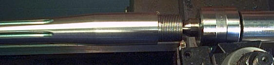
Well Shazamm. A gent could make anything he wants to out of the words in this thread! Interesting reading to say the least. Anyway, some photos below of a 98 action I use as a proof gun with a strain gauge system. I think it came from the Gun Show near Tacoma WA maybe 30 years ago, was in a big box of M98 parts I bought. So here goes: Receiver ring is 1.372".     Receiver ring marked Model 98/85 with the American Eagle crest.  Side of receiver marked Federal Ordnance SO El Monte CA USA So I am guessing Federal Ordnance ground the ring down. Any better guesses? Overall the action is in very good condition and has a full 3-1/2" magazine cutout. Without no redneck grinding on the lower lug. Thinking about using it for another 400 H&H rifle. Threads are the full 1.1 inch M98 thread. Edit: I have had this action/barrel up to 65,000 psi with no damage. Interesting huh? With a 30 foot lanyard of course. And yours truly standing behind the pickup.   | |||
|
| One of Us |
Well for you James here is a more accurate depiction of that second cut, removing even more material from that critical X section.  | |||
|
| One of Us |
WoodHunter are you using a home made strain gauge system or did you purchase one? Nathaniel Myers Myers Arms LLC nathaniel@myersarms.com www.myersarms.com Follow us on Instagram and YouTube I buy Mauser actions, parts, micrometers, tools, calipers, etc. Specifically looking for pre-WWII Mauser tools. | |||
|
| One of Us |
Keep grinding and up the juice to 3 of Stuart's 86ksi proof loads. I wanna see what happens. I like your test sled, 12" Miscellaneous Channel? | |||
|
| One of Us |
I totally misread the end mill detail. Now I have to ask: wouldn't it be easier to have cut that relief AND the C-ring face with a boring bar followed by threading? Kind of a twofer set-up? Believe me, I have no want of a wee-wee contest, I'm just curious because I don't know! | |||
|
| One of Us |
Federal Ordnance in El Monte, CA was known for making counterfeit Springfield 1903 /03-A3 using investment cast receivers. They didn't mark them fraudulently, i.e. M1903 U. S. Springfield, U.S. Remington 03-A3, but I believe they marked them Federal Ordnance 03-A3. They weren't known to be weak as far as I remember. I don't know if your's is a converted military mauser or an investment cast copy? PA Bear Hunter, NRA Benefactor | |||
|
| One of Us |
Well that is basically what they did with a boring bar in a lathe. But then they needed an offset clearance cut only on the extractor side. So they could have offset the receiver in the lathe or moved it to the mill and made another cut with dovetail cutter. I wasn't around when Mauser did any of this but my take is based on the cuts I see, how I would do it and the book by Colvrich, on the manufacturing of the Springfield rifle. https://ia802205.us.archive.or...esrifl00colvrich.pdf Around page 58 describes the shaving of the lugways. | |||
|
| One of Us |
Each manufacturer did things slightly differently, but on a whole, the basic idea was the same. The receiver threads were thread milled, not turned on a lathe. Much faster, and in mass production, the more accurate of the two short of using a tap. The bolt ways were put in with "Upright Shaving Machines". Relief cuts by "circular shaving machines" Keep in mind, mass production at this time period used dedicated machinery and setups. Machines varied over the years, but one example, providing 170 rifles per day of 9hrs required 104 machines just to make the receiver. Nathaniel Myers Myers Arms LLC nathaniel@myersarms.com www.myersarms.com Follow us on Instagram and YouTube I buy Mauser actions, parts, micrometers, tools, calipers, etc. Specifically looking for pre-WWII Mauser tools. | |||
|
| One of Us |
I just inspected some L/R actions - 1916 GEW DWM 1908 Brazilian DWM & Oberndorf 1912 Chilean Steyr 1909 Arg DWM 1937 Mauserwerke Vz24 X 3 Brno late war All except 1 (GEW),the relief cut is the same diameter all the way around and finishes up exactly the same depth as the extractor side lug way. The GEW had a very small extra cut to clear the chips, no more than .005" deeper than the R/H lug way. Measuring the receiver rings you get very close to - O/D - 36mm Wall thickness at extractor - 4mm 36 - 4 - 4 = 28 mm or 1.1" Sounds familiar. To me it looks like the relief cut is major thread diameter. | |||
|
| One of Us |
 VZ24  GEW  DWM 1908 | |||
|
| One of Us |
Why on earth would you put the center of the .535" OFF center??
| |||
|
| One of Us |
Metal, measuring the lugway wall is not an accurate method to determine the wall thickness at the relief cut. You can clearly see in most of your pics the relief cut at the extractor is deeper than the lugway, and the lugway is deeper or a larger diameter than the threads. So they can't all be equal. | |||
|
| One of Us |
Well because a relief cutter with a radius of 0.535 if centered would cut a 1.070" diameter, with the major thread diameter of 1.100" that wouldn't cut enough thread relief let alone extractor relief. Now would it? The right lugway is about a 0.560" radius, how do you cut relief for the shaving cutter with a 0.535" radius cutter w/o offsetting it? | |||
|
| Powered by Social Strata | Page 1 2 3 4 5 6 |
| Please Wait. Your request is being processed... |
Guns, Politics, Gunsmithing & Reloading Gunsmithing

Visit our on-line store for AR Memorabilia