 Guns, Politics, Gunsmithing & Reloading Gunsmithing
 Go | New | Find | Notify | Tools | Reply |
| M2002 PH (Professional Hunter) by MRC | Login/Join |
| <Rod@MRC> |
Question: Given a receiver ring diameter of 1.505, how high above a tangent to the O.D. of the ring should the plane of the forward square bridge lie? Barrel threads are 1.125 V16tpi. | ||
|
| <JBelk> |
Rod-- I'd like to see .100 if it's a wide bridge. That leaves room for a recoil shoulder for dovetail mounts but low enough to leave plain. The M-21 came today. | ||
|
| one of us |
Rod, I like Jack's suggestion. A positive recoil shoulder on top of each bridge would be good to withstand those big bore calibers. Here are two snapshots of one of my own unfinished actions. I have played with a lot of conceptual designs with CAD but could not come up with anything better than the Mauser design. I only got these snapshots at home, as most of my stuff are at work. I do not design rifle action for a living but just play around in CAD with concept modeling for fun. This particular sample has a 1.625" diameter ring and a 1.1875" diameter barrel thread. The two square bridges raised up to about .125 in from the tangency of the receiver ring if I remember correctly. I look forward to seeing your final design of the PH action. Thanks! | |||
|
| one of us |
Hey Rod, Are you going to make both bridges at the same level just like the CZ 550 Safari? I am not sure why the M-70 got an offset bridge between the front and the rear. It may have something to do with weight reduction but weight is a good thing with a big bore action like the PH. Thanks! | |||
|
| <Rod@MRC> |
Another question: If the bridge width, (both front and rear) is .850 across the flats, is this enough width to drop vertically into a radius that terminates at a tangent to the ring? (Scalloped effect) To be honest, I sent the CAD guys back to the board today. Drawing a straight line from the edge of the flat to a tangent on the ring made the action look like a brick. We DO need a little elegance here too. We want some flowing lines. What about rounded edges at the edges of the flats(like Mingo's view)? Ours are currently sharp. What if we scallop the leading edge of the front bridge but keep the radii forward of the recoil lug (so custom gunsmiths can whack it flat by shaving the ring back to the lug)? Both bridges are the same height, which makes the rear one truly massive. | ||
|
| <JBelk> |
Rod--- Try a .5 radius between the top of the square and the tangent of the ring on the sides and .187 on the front as you said. That way the ring can be faced back and a quarter rid butted up flush. Keep a 90 degree corner or better on the bridge. .850 width is just enough for the CZ size rings and we need the corners. Keep the tops parallel with the bore-line. That way the rings can be the same height......like all the custom rings are. | ||
|
| <JBelk> |
 CZ-416 Rigby action. Actual dovetail width is .762. | ||
|
| One of Us |
Jack, what is the width on the Melani rings? Would be great if they could be accomodated. Rod, these are a CNC copy of Tom Burgess's BRNO 21/22 rings. They have two recoil lugs on each ring and they can be removed (milling) if less are sufficient. They also do not have to slide on. There is enough movement in the camming action of a quarter turn to lock the rings tight and allow it to be removed laterally without sliding them on, which can get tiresome at times. | |||
|
| one of us |
Rod, Instead of having a vertical drop from the bridge to the receiver ring, why not have the bridge taper down tangent to the receiver ring on each side. I did a quick model to get the concept across and here is the picture. If you want it to look even more elegant, then why not taper both the front and the rear of the receiver to give it a more aerodynamic look. The geometry will get more complicated but your solid modeling system should be able to handle it. I did have a concept model like a while back but I am not sure if I can find it in my archive database. I can recreate it if I have time. Thanks! | |||
|
| one of us |
Hi Jack, Are you refinishing that CZ 550 action? It got a nice three position safety. I wonder how much you charge to do do the refinishing and putting on a three position safety. Are you retired or still working on guns? Thanks! | |||
|
| <Rod@MRC> |
We're shortening (slightly) the length of the bridge tops (from the rear) to bring the profile of the receiver ring and rear bridge ring into play. Used your numbers Jack on the side and forward radius of the front bridge and the sides of the rear bridge. Concave compound radius in front of the front bridge. The rear of each bridge is a compound "flat" curve that blends the square top into the rounded receiver (visualize that!) This is to keep polishing from becoming a nightmare. Also, when I asked the question "How much metal is left on the magazine well sides when we machine the pocket for a .505 Gibbs magazine?" I got a moment of silence during the calculation and then ".010." Oops. Furious scribbling in note pads. Fixed tonight. Chic, I saw Tom's rings about a couple of weeks ago. I think we're OK for both width and material to carve out the pockets on the offhand side. Mingo, I think what you've suggested is pretty much what's happening this evening. | ||
|
| <Rod@MRC> |
The following images were generated from our CAD file. While this iteration is not the end-all for the design, it's good enough to create some models on the RPS system. One was started tonight. If it passes muster, we'll send it on to Ruger to be cast, and later to machined into a working receiver. You have to love this technology - from concept to design to metal to pulling the trigger in about sixty days. Feel free to throw stones or roses. All input is appreciated.    | ||
|
one of us |
It looks very pretty. I need to start saving money. | |||
|
| <Kboom> |
Very good looking action. I think you need to provide a way of using a readily available scope ring. This would greatly enhance it's utility. | ||
|
| one of us |
Rod, I'm still willing to be a "field tester"? | |||
|
| <338Lapua> |
Have you figured the cost on one of these yet? What type of bases will it accept? What type of stock will it be compatable with? Just curious. Jim | ||
|
| One of Us |
No offense, but I like the "look" of the Granite Mountain action best. I also like a genuine model 98 bolt release and ejector rather than that model 70 deal. | |||
|
| one of us |
Rod- I suggest you take a good look at the Vektor action and copy as many of the good features as you can. The Vektor is rediculously expensive as it's machined out of a chunk of EN27. If you can build a similar action and sell it for half the cost you will be king of the big bore action makers.The bridges on the Vektor are perfectly sized for leaving alone or machining in Talley mounts. The action screw on the tang is hidden making for a smooth profile and most importantly it will accept 3.850 inch long cartridges like the .505 Gibbs. I would suggest you use a .750 diameter bolt so there would be some rim left on the .640 rim cartridges like the .505 Gibbs or 585 NYATI. You could even make a .577 T-Rex on a bolt like this. I really like your dual receiver recoil lug design( I just hope you can get it out of the glassbedding without using dynamite or a torch). If you send me one ,I'll build a .600 OK on it and test-er -out properly for you. | |||
|
| <Rod@MRC> |
Kboom: I might agree if there was a common preference in which ring to use. As it is, we might please one and get lynched by many. Still any competent gunsmith could drill and tap 8-40 for a set of gunmaker bases (shudder). Al: I�ve a feeling we�ll have to select that job by lottery. 338Lapua: The target bill-of-materials cost should allow a price somewhere around $600. There are still a lot of assumptions that must prove out, but I think this is a sound estimate. We�ve shaped the bases based (pun alert) on input from several custom builders � allowing them enough metal to put on their favorite choices. If we�ve missed by a little, we can easily correct that before production begins. There are no production stocks that fit (that I know of). However, once the shape is frozen, we�ll provide drawings to stockmakers (McMillan, Boyds) and custom gunsmiths who want or need them. 500grains: not a problem. Personally, I�m not a fan of the M98 mechanism, although I like its location. And I�m less than keen on a split left lug, but it avoids other tradeoffs. I agree that the M70 bolt release had to go. Not having a gas flange would unconscionable, and the M70 shroud lock and bolt stop get in the way. Robgunbuilder: We�ll look at the Vektor. Thanks for the suggestion. I think we may have the Talley�s covered. Check earlier in this thread. If by action screw, you mean the rear guard screw, I agree. Ours is blind. The hole you see in the picture is for the sear. This action as a 4.025in magazine box and that means it will reliably feed cartridges approaching 4.00 inches in length. The Bolt is .805 in diameter and shaped to accept a .646 bolt face for the .505 Gibbs. There is enough meat in the lower receiver sections to properly hog out the magazine pocket for proper stacking of three in the box (.505 Gibbs), four in the box, .416 Rigby, and five in the box (375H&H). Dual receiver lugs? --- I think that�s Mingo�s design concept and we can�t afford the royalties. | ||
|
| one of us |
Rod, It would look a little sleeker as the Ruger Magnum action does, if a larger radius was made on the left side bolt opening as it tapers up to the bridge in the front and rear. I'd like to see the double lug feature on this big action too. | |||
|
| <JBelk> |
Brent--- Just a word on double recoil lugs. (Not picking on you mingo.) The transfer of recoil energy from metal to wood creates shear stress on the stock area at the boundaries of the recoil lug. The ability to handle this stress depends on the amount of stock material behind the lug. By chopping that area in half with an extra lug the strength is actually reduced considerably. Probably the best recoil system every devised for hard kickers is the Ruger 458 M-77. It uses a yoke on the receiver to transfer the recoil up the forearm to a lug in the fore end wood. This gives 4 inches or so of stock between the recoil lug and the next opening in the stock. The Mauser system was pretty much perfect until we changed triggers. In the M-98 the recoil is spread from the receiver to the bottom metal with the socket around the front action screw and uses the magazine box back as a VERY large recoil area......until we cut it away for a bigger trigger. I see no problem whatever with handling recoil in the currently shown Montana Pro action. It's essentially the same as the Model 70.....and they just DON'T break from recoil if the bedding and stock material is even half way decent. Winchester increased the depth and distance of the recoil area so they could use softer and less strong American Walnut.....and it worked. Rod--- Purely from a looks point of view, I'd continue the rear bridge flat all the way to the receiver opening and then drop it straight down to the bolt. That angle looks too much like a Colt Sauer..... YIKES!! did I say that? Sorry! Most of the time the rear scope ring needs to be as far forward as possible, too, so it would serve a mechanical as well as asthetic purpose. Chic--- The Melanie rings will fit this wide dovetail with some room to spare. I can't think of a better ring for the snot slinger calibers. I'd leave both recoil shoulders on the rear ring so the front of the ring would be flush with the front of the rear bridge (see above) and leave a .025 shoulder at the front of the front bridge as a recoil stop for that ring. Any caliber that loosened that system should have been mounted on something with tracks or wheels. | ||
|
| new member |
Rod, Thanks for looking for inputs and keeping people informed on your progress. On the PH action the front of the front bridge appears to be concave while the other tapers all look convex. It might just be a trick of the rendering but I think the action would look nicer if all of the tapers were concave like the front. Thanks again, TBP | |||
|
| one of us |
Rod, Nice prototype rendering! Speaking of the front and rear edges of the bridges, I think it would be best if it were not contoured at all. That is, make them pendicular to the plane that is tangent to the top of the reciever ring(s) (I think I'm reapeating what a few others have input... sorry). I think that if the front and rear edges of the bridges are left perpendicular the functional purpose of providing a continuous sight plane will be optimum. Optimum compared to concave or convex contours... Hey, I've got a thing for iron sights. By the way, the rear mauser style tang makes me happy! Keep up the good work. David Schnabel [ 12-15-2002, 02:26: Message edited by: DavidReed ] | |||
|
| <Rod@MRC> |
Brent Moffitt: I've read your post several times, and I'm thinking you're talking about the ejection port on the offhand side of the receiver - sort of the top cover to the left lug raceway where it blends into the bridges, yes? You want that arc more gradual? A larger radius? That would add quite of bit of weight (good and bad points) and mass to be cast (bad points). And comments out there on this idea? Jack Belk: Thanks for the hint on the rear ring mounting surface. Colt Sauer = insult? You lost me there (limited history lessons, I guess) TBP: actually, on the rear edges of the bridge are NOT concave. And maybe they should be if we want "recoil" edges at the rear of the rings. We were thinking of making the polisher's life easy here. DavidReed: a pass or so back, they were squared off. I think it looked a bit too much like a block. A brick was the actual term I used. But, with convex curves blending into a vertical wall just a bit below the "sight plane" or mounting surface of the bridges might accomplish the same optical effect, yes? And give recoil edges to resist forward ring movement. We'll have to look at this. [ 12-15-2002, 05:17: Message edited by: Rod@MRC ] | ||
|
| <JBelk> |
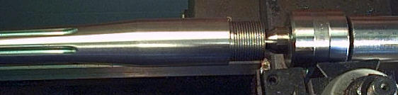
Rod-- I can think of nothing more ugly than a Colt Sauer with those truncated beehive scope bases buffed 'til they look like lumps of road tar. When I mill a scope base for dovetail rings like Talleys, I leave a .025 to .050 raised stop at the front for the ring to butt up against. Otherwise the scope will fall off the front of the base from recoil.  This is on a 9.3x62. | ||
|
| one of us |
Brent Moffitt: I've read your post several times, and I'm thinking you're talking about the ejection port on the offhand side of the receiver - sort of the top cover to the left lug raceway where it blends into the bridges, yes? That is what I was refering to. I like the concave look on front and back of the bridges a little better too. This will use the Winchester trigger also correct? Looks very nice, can't wait. | |||
|
| One of Us |
Jack, The dovetail will fit but the recoil lug is much thinner than the Burgess rings. It looks like very little of it will catch the contour of the bridge. May need to weld on an addition on the inside. Or you may be able to utilize a recoil shoulder like you show in that photo. BTW, I like the stamp. [ 12-15-2002, 09:12: Message edited by: Customstox ] | |||
|
| <Rod@MRC> |
Jack: misunderstood. I was thinking the ring hung over the leading edge of the front bridge and that didn't make much sense. While thinking about the front edge of the rear bridge, I studied one of the earlier iterations. What I didn't like about dropping directly to the bolt bore with a sheer surface was the junction of the left ejection port flange (the top raceway cover Brent was talking about). It needs a transition I think. Perhaps a ghost of the rear ring diameter (like the bottom rendering) to sweep into. What if we back away just a smidgeon and fell into that ring o.d. with a bit of vertical drop and then a large concave radius? It would start from a square edge like the front bridge. Aesthetics and function combined. I'm thinking we could accomplish this from only .025 to .030 back. Problems? Brent: From the LA, this will use the same trigger, sear, bolt release, sleeve lock as many springs as we can make happen, the MIM'd safeties and that's about it. We'll need a new extractor, one with an semi-dovetail foot and a larger i.d. The cocking piece grows a .0525 deeper tail to meet the sear from a higher elevation. And it will have .400in striker fall as opposed to .265 for the M70. Chic: does the recoil lug engage the rear edge of the bridge? What's needed to provide more engagement? [ 12-15-2002, 10:33: Message edited by: Rod@MRC ] | ||
|
| <JBelk> |
Chic is right---I hate it when that happens. The rings made by Malanie are .950 outside width. The recoil lugs hang down .125 below the dovetail.   That means in order to machine the bridges of the Pro Hunter to exactly fit these rings the flat top should be 1.000 wide and allow room for the locking lug socket to end .225 below the top surface of the bridge. The actual dovetail is .100 top to bottom. Chic posted a good picture of one of these mounts with the ring in place. | ||
|
| <Rod@MRC> |
Those are good looking rings. I can't tell from the two views, but do they clamp the scope securely independantly of the levers? In other words, would they make a good QR mounting? Where is Chic's image posted? I'm thinking .100 might actually look better, since the receiver rings are much wider. Looks like our first prototype is obsolete already when the model is less than 24 hours old. | ||
|
| One of Us |
Rod here is a photo of the setup. Morris did the bases for me in his shop in Utah.  | |||
|
| one of us |
Rod- One thought. Look at the picture of the Vektor action I posted on my 505 Gibbs thread on Big Bores. Consider the curvature of the rear tang. Make sure, it's angled sufficiently that the bolt will not strike the wood of the stock on a rapid cycle sequence. This seems simple, but is hard to avoid on actions whose tang is not properly contoured. -Rob | |||
|
| <JBelk> |
Rod--- These rings are a natural for the Pro Hunter, IMO. I was thinking you had Mr. Burgess tied to the design table up there and he's the wizard that came up with this design, I think. This ring holds the scope completely independantly from the clamping process. One whole side moves smoothly about .070 with a 90 degree rotation of the locking lever. They're adjustable for dovetail size to get the final clamp at the proper lever position. The rings I have are for the M-21 you looked at. To use them on that action I would cut off three of the four recoil lugs and leave the left rear lug intact to engage the notch milled in the dovetail. The lowest mount that can be made to fit this ring on a 1.400 dia. M-98 is .100 above the tangent of the ring. Someone more talented than me in the mysteries of mathematics will have to transpose that figure to the bigger ring, but I'd think it would be .115 or so. It's hard to make mounts that low and that wide without soldering them on the ring. The recoil forces are way out on the wings of a very thin part. They're perfect for an intergral bridge, though. [ 12-16-2002, 10:30: Message edited by: JBelk ] | ||
|
| one of us |
No offence guys, those look like quality rings, but I've never liked the look of the rings that clamped at the top. I hope there won't be a problem milling a 20-40 MOA integral base and cross slots into this when the design is finished so the Weaver style rings that many use will work too. | |||
|
| one of us |
Burgess Lever Release Q.D. scope rings. Brent, the rings are split so's you can get them on the scope tube. They were meant to be bolted up at bottom tighter than a bull's a..... ah uh they were intended to be tight enough with a surface ground fit at that point so that the ring could be thought of as solid at that locus. There being no other place from purely an engineering stand point that distributes the clamping force equitably for the requirements to be met the clamp ears ended up on top. I never have liked those clamp ears up there either, but after several hundred wasted hours chasing after ultimately failed solutions I returned to the ears on top. Most serious D.G. hunters liked the idea of a mounting assembly which would return from where it left repeatedly and under trying and often miserable conditions. They also desired levers instead of coin slotted knurled knobs. If you split the rings sideways like L&S and most of the rest the lever must protrude far enough away from it's axis to clear those clamp ears that it ceases to be functionally worthwhile, but such a clamping system would be vastly easier to make. That the system tends to work as mechanically intended is evidenced by the various knock-offs floating around out there. One thing apparently NOT copied is the Walking Parallelogram feature designed to make mine tighten up in firing. Subtle but there. The second recoil stop used on DGR's was inspired by the weighty European scopes coated with Teflon like material which allowed the scope-not the front scope ring-to slip. Leupolds didn't slip. That slicky scope surface did do as intended. Water slid right off the tube in rain snow or sleet. Where it was far enough away from the scope to be of no worry. Down in the action of the rifle and the stock and... Quadruple recoil stops are still better than the raised front ledge end stop or the cross rod methods. If scope tubes were available with bottom rails profusely, why then the esthetic and cosmetic styling would be solved. | |||
|
| <Clint> |
Rod, This entire thread sounds intelligent and wonderful. None of you can realize just how grateful I am for all thi discussion. However, Rod I just want to make sure that when the dust settles (0r the wax melts) Until then, I'm looking forward to that LH Long Action. Safe Hunting | ||
|
| One of Us |
System 98, Tom, where is this "walking parallelogram" on your rings? Or would I even recognize it. I have a set of yours that I got from Maurice Ottmar. They are works of art. I have them on a BRNO 22 in 7X57. | |||
|
| one of us |
Yo Chick, Find an old cigar box about ready to lose its bottom,re-adjust with a square so that sides and ends are square to each other, measure across from one long side to the other to get the width,carefully corner the box against something solid like the base of your loading press, then push on the diagonally opposite corner with enough force to knock the box out of square. Measure width again. Now the long sides are closer together. The walking paralellogram. The recoil tab stops forward movement during recoil,but the rest of the ring can and does slide albeit imperceptably, yet tightens the ring. This is noticable on the big thumpers in that more effort is required to release the levers. Oddly even without tab the difference in the metals used causes the same effect. A calibrated ammount of difference exists in the diameter of the strain screw as to ring body and clamp plate. The screw and plate are at low end of spring temper which assists. Lee (once big in potatoes) was here tonite, says Hi. to you and Jack. I showed him this forum and the mock up of rings for the CZ 22 LR and the Hornet/ 222. They are extension types and It required a lot of cut and try to get the weight equal to the regular rings. Also got to look at the Wax Master of the PH by MRC. You will all like it. For those who are concerned Rod says that they are instituting the draft where it counts stockwise. They seem surprised over there everytime I point out something that with firearms design is a genuine innovation of worth .I am always told that it was the only solution to make sense. Mebbe so but damned unusual in this day and age. | |||
|
| one of us |
Tom is it possible to buy these mounts. Mark | |||
|
| Powered by Social Strata | Page 1 2 |
| Please Wait. Your request is being processed... |
Guns, Politics, Gunsmithing & Reloading Gunsmithing

Visit our on-line store for AR Memorabilia
| View $GS_USERNAME's Public Profile | |
| Add $GS_USERNAME to my Buddies | |
| Add $GS_USERNAME to my Ignore List | |
| Invite $GS_USERNAME to a Private Topic | |
| View Recent Posts by $GS_USERNAME | |
| Notify me of New Posts by $GS_USERNAME |