 Rifles Lever Action Rifles
 Go | New | Find | Notify | Tools | Reply |
| Winchester 71 Disassembly/Assembly Instructions | Login/Join |
| One of Us |
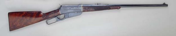
By: Bob Nisbet The following is my process and is based on actual disassembly and reassembly of my model 71 which was manufactured in 1950. This procedure will allow you to completely disassemble a model 71 receiver, remove the bolt and other parts, and reassemble the rifle. Remarks: · The rifle shall be verified to be unloaded, both in the chamber and magazine tube. · Wear safety glasses during steps where springs may pop loose. · The rifle hammer shall be down (un-cocked) during most of disassembly procedures. · The lever shall be manipulated as necessary to accommodate disassembly. · This procedure requires the bolt and lever to be removed as an attached assembly. If the bolt is to be disassembled, it must be done after the bolt assembly with lever are removed as a unit. · It is recommended that parts be identified as the disassembly proceeds. Recommendation is to use masking tape to mark each part, being sure to specify if the item was from the left or right side, what faces front or left or right, etc. Marking is not noted in these step by step instructions. · Clean or wipe parts as necessary. · Perform the disassembly on a clean surface, to avoid losing small screws, cross pins, or the miniature trigger springs. · These procedures specify removing the hammer spring abutment keeper, which is done by drifting a pin that is installed through the lower tang, thereby releasing the energy in the hammer spring. Required tools: A. Gunsmith’s screwdrivers – Three sizes. B. Brass or bronze drift punch, approx. 0.187 diameter. (Used to remove vertical locking bar roll pin and split pin.) C. Brass or bronze drift punch, approx. 0.060 diameter. (Used to remove hammer spring keeper (abutment piece) drift pin from lower tang.) D. Steel Wire, Allen Wrench, or Paper Clip – Diameter of 0.060 to 0.070 with a right angle bend at one end, with the length of the bent element approximately 0.080 (Used for hammer bushing removal.) E. Pliers (Used to make tool item D, the bushing removal tool and to remove the allen wrench from the hammer spring guide during reassembly). F. Allen Wrench, or Paper Clip – Diameter of 0.060 to 0.070 with a right angle bend at one end, with the length of the bent element approximately 1 inch (Used for hammer spring retention). G. Masking tape (Used to mark and identify parts as they are removed and also used to hold trigger group during reassembly. H. Pen for marking masking tape. I. Paper towels or equivalent for wiping off excess oil or removing dirt. J. Rag. (Used to restrain the hammer spring and its keeper during disassembly.) K. Hammer and hammer spring pre-load reassembly tool. A metal piece with a hole drilled ½ inch deep and a diameter that will accept the hammer spring guide. The tool will have a notch extending 1/8th inch along and into the hole, which will allow an allen wrench to be inserted into the hammer spring guide’s vertically drilled hole near the end of the hammer spring guide. DISASSEMBLY: STEP 1: Remove the tang screw and pull the butt stock straight off to the rear. The tang screw goes all the way through and screws into the bottom tang. STEP 2: Remove the loading port cover screw and cover assembly from the right side of the receiver. STEP 3: On the right forward side of the receiver, remove the receiver screw that secures the guide piece that limits travel of the right vertical bolt locking bar. There is a small round spacer under the receiver screw that secures the travel limit piece, so be sure to capture and retain it. Open the bolt and then manipulate the travel limit piece until it is remove from the receiver. STEP 3: Remove the hammer screw from the left side of the receiver. STEP 4: Preparation for hammer removal. As part of step 4, be sure to place a rag or towel over the hammer spring to prevent it from being launched out along with its keeper. Removing the hammer spring, will also release pressure on the trigger springs, allowing them to fall out of the receiver. (My model 71 has two springs (one short and one long). In the next step, as the hammer spring is released, be sure to capture it, its keeper, and both of the trigger springs. STEP 5: Wear safety goggles for this step! You will be releasing significant compression of the hammer spring. The hammr should be down for this step. Using the small drift punch, drive out the pin from the mid-section of the tang that holds the hammer spring keeper. Drive it from left to right. It need not be driven all the way out. Driving the pin past the far side of the keeper then retracting the drift punch will free the hammer spring keeper and allow the removal of both the hammer spring and its keeper. STEP 6: Using tool item #D, made from the wire or paper clip, and accessing from the left side of the receiver, use the tool to reach inside the hammer screw hole to remove the hammer screw bushing from inside the receiver. The bushing has a small hole, approximately 0.078 in diameter drilled at 90 degrees to its length, near one end. To remove the bushing you will insert the bent tool leg through the hammer screw hole and engage the bushing hole. When engaged, pull the bushing out. The bushing will come out with very mild resistance, since the hammer spring is not under pressure. STEP 7: Remove the hammer and spring guide rod assembly from the receiver. At this point it is recommended that the hammer safety notch be inspected to verify that the safety notch is not broken . STEP 8: Remove the lower tang, with trigger parts remaining in place. The tang assembly will usually come out by asserting rearward pressure while lightly and repeatedly pressuring both to the left and right. It may require light tapping toward the rear. STEP 9: The lever and two vertical locking bars are held in place by two opposed pieces, a roller bushing and a split pin that is pressed into the roller bushing. With the action open, turn the rifle onto its right side and place a support under the right vertical locking bar in the area of the roll pin, being cautious to select a support that will allow the vertical locking bars split pin to be drifted out toward the right side. Use the 0.187 punch to drift the split pin out from the roller bushing (between the two vertical locking bars). The split pin looks like it has a screw slot, but in fact the slot is the slit in the pin. The slot is not a screw head! (The split pin is easily removed with light but firm taps on the punch. Removal will not damage the split pin and it can be reused.) When the split pin and bushing have been removed, then remove the left and right vertical locking bars. Both bars should come out easily. The right bar had a pivoting travel limit piece attached to the receiver that limits bar travel and this piece must have been removed in step 3 before the bar can be removed. STEP 10: As a unit, migrate the breech bolt and lever partially toward the rear. With the space made available by moving the breech bolt and lever to the rear, carefully manipulate the cartridge carrier out of the receiver. STEP 11: Move the breech bolt (with lever attached) to the rear until it is fully clear of the receiver, then lifting as a unit, lift and migrate the assembly out through the top of the receiver. Basic disassembly is now complete and you have access to the interior of the receiver and all removed parts. Optional: Breech Bolt Disassembly STEP 12: For breech bolt disassembly, lay the breech bolt (with lever attached) on its side and use a drift punch to drive the lever pin out toward the right, while holding light thumb pressure on the ejector. The cartridge ejector spring provides only mild pressure and is not difficult to hold. To remove the extractor, drive its small cross pin out and lift out vertically. The extractor is not under significant spring tension. To remove the firing pin, at the rear of the bolt drive its small cross pin out and slide the firing pin out to the rear. Note the orientation of the ejector and firing pin cutouts. The cutouts will need to be correctly oriented for reassembly. RE-ASSEMBLY PRE-ASSEMBLING THE HAMMER SPRING & HAMMER STEP 1: Wear safety goggles for this step! You will be heavily compressing the hammer spring. Using a cloth over the spring should capture it if it escapes. Be careful that the spring does not escape and fly off. Locate the hammer assembly and hammer spring, then insert the spring onto the guide rod. (It will extend beyond the end of the guide rod.) Insert tool K into a vise or secure it so that it will not move under heavy spring pressure. With the hammer spur toward the top and aligned with the notch in the tool, compress the hammer spring until the guide rod enters the hole in the tool and the vertical hole in the guide rod is viewable in the tool notch hen quickly insert the short side of the allen wrench into the vertical guide rod hole and release the pressure on the hammer/spring assembly. You will have thereby captured the hammer spring on the guide rod. The hammer spring will be heavily compressed. PRE-ASSEMBLING THE TRIGGER, TRIGGER SPRINGS AND HAMMER SPRING KEEPER (Applicable to a 2 piece trigger) STEP 2: The two piece trigger actually has 6 parts, the trigger, the sear, a sliding release, 2 springs, and the cross pin. This step assumes that your trigger, sear, and trigger sliding release parts are already installed on the tang unit. Locate the tang assembly, 2 miniature trigger springs, the hammer spring keeper and the keeper cross pin. While holding the tang assembly, use one finger to lightly press and hold the trigger in its rearmost position. While holding pressure on the trigger, push the release slide piece to the rear. You may notice a click of the trigger during this step. Using the tape, wrap some around the trigger and extend the tape around the back of the tang, being sure that pressure was held on the trigger throughout this process. Install the short trigger spring vertically into the recess in the sear (right side), then lay the long spring down and engage the recess in the sliding release (left side). Take the hammer spring keeper and place it such that its 2 recesses engage both springs, and while in this position, insert the keeper cross pin. If done correctly, the miniature trigger springs will be captured in place. If not, perform the procedure again. When completed, set the trigger assembly aside. PRE-ASSEMBLING THE BREECH BOLT AND LEVER STEP 3: Assembling the breech bolt and its parts is simple and requires no heavy springs that will present a challenge. This procedure does not address breech bolts with integral peep sight. Place the extractor into the slot on the top of the bolt and install its cross pin. Install the firing pin from the back, noting the notch orientation at the rear, then install its cross pin. Put the ejector spring onto its guide and install the ejector into the bolt and hold lightly with your thumb. Take the lever and insert it into its recess in the bottom of the bolt, then with thumb pressure on the ejector from the front, press the ejector into the bolt and install the large lever holding cross pin. STEP 4: Insert the cartridge lifter into the receiver. STEP 5: Take the bolt and lever assembly and gently install it into the receiver from the top by manipulating it until the lever is all the way through and you are able to slide the bolt into the receiver. STEP 6: Install the pre-assembled hammer parts into the receiver, being careful that the allen wrench continues to hold the hammer spring in place. STEP 7: While viewing parts through the hammer screw hole from the left side, manipulate the hammer assembly, lower tang assembly, and cartridge carrier until all the holes line up. The hammer spring guide must also engage the rear guide hole in its keeper. When aligned properly, insert the hammer bushing from the left side, being sure that the bushing side hole is toward the left. Alignment may require internal part manipulation with a punch or other improvised tool. When alignment is correct, the bushing will with little pressure. As alignment is manipulated, be sure that the hammer guide remains in its keeper hole. When all the parts are aligned and the bushing is in place, install the hammer screw. STEP 8: Using the pliers, remove the allen wrench from the hammer spring guide and verify that the hammer can be cycled normally, but the sear will not engage. Then remove the tape from the trigger and tang assembly and verify that the hammer can be cycled normally, and the sear will engage and release when the trigger is pulled. STEP 9: Insert the left and right bolt locking bars into the receiver and with the bolt partially opened, insert the guide piece that limits travel of the right vertical bolt. This will require some bolt movement and part manipulation. Align the guide piece with the receiver hole and insert the ferrule and screw and tighten. STEP 10: Install the loading port cover. Bob Nisbet DRSS & 348 Lever Winchester Lover Temporarily Displaced Texan If there's no food on your plate when dinner is done, you didn't get enough to eat. | ||
|
| one of us |
Hello Bob. You missed step 4B. With the hammer cocked insert the punch or paperclip nose into the cross hole in the end of the ( # 4271, Hammer spring guide rod )This hole will be visable behind the ( # 4471 Hammer Spring Abutment ) once the punch/paperclip is inserted into the cross hole, gently let the hammer foreward. This then capivates the hammer, mainspring unit, and mainspring abutment, as a unit. Regards. Jim Wisner | |||
|
| One of Us |
Thanks Jim. Your suggestion diminishes the possibility of any parts flying out. Mine also worked, but not as elegantly. To the best of my knowledge there may not be anyplace else where these instructions are published (without purchasing a Winchester Repair book), which most 71 owners are unlikely to purchase. Bob Nisbet DRSS & 348 Lever Winchester Lover Temporarily Displaced Texan If there's no food on your plate when dinner is done, you didn't get enough to eat. | |||
|
| One of Us |
I found an old disassembly guide online that was from a (very) back issue of American rifleman that was also very helpful. Using Bob's instructions and those, I was able to move a bolt peep from one 71 to another. One of those rifles appeared to have been glued together with 71 years of WD-40 application Without reassurance I would never have had the confidence to put the amount of force on the tang that was required to get it to slide out. _______________ DSC NRA Benefactor | |||
|
| one of us |
Bob. The very first 71 I tore down I did it your way, and once apart I saw the pin hole and ??? Dad became a Winchester service station in 1973, so I went and pulled the service manual and the dim light in my head got brighter From then on I started reading all those old manuals, even have some of them left over from when the Gun shop closed in 1994. JW | |||
|
One of Us |
Is the process much the same for the '86? If so, I must remember this thread but try not to ever need it | |||
|
| One of Us |
I am not familiar with the 86, so I can not comment on those. Bob Nisbet DRSS & 348 Lever Winchester Lover Temporarily Displaced Texan If there's no food on your plate when dinner is done, you didn't get enough to eat. | |||
|
| one of us |
The problem I have is Ive dismantled the 86, 71 and 94s in the past, but the need arises so seldom that I forget how, so I have to start all over with a guess and by gosh, and a fading memory!! I can disassemble anything, probably a nuclear bomb, getting it back together is a hell of a job, and not always successful..I did these things as kid growing up and disaster was usually just around the corner.. Ray Atkinson Atkinson Hunting Adventures 10 Ward Lane, Filer, Idaho, 83328 208-731-4120 rayatkinsonhunting@gmail.com | |||
|
| One of Us |
An item I did not mention was the Bolt Peep Sight. It may be obvious that when disassembling the bolt, that the Peep Sight needs to be removed. To remove it, the Elevation knob must first be removed before the retaining cross pin is pushed out. Also, note that the hidden end of the Elevation Knob threaded rod has a flared end and which during normal use, prevents the Elevation Knob from being fully unscrewed from the Special Nut which is captive inside the bolt. That nut floats (rides) on top of the firing pin. The flare may be so well done that the Elevation Knob threaded shaft could be sheared when trying to remove the Elevation Knob. Using a quality lubricant may assist the shafts ability to press out the flare, but it may take numerous incremental turns in and out to accomplish the release. When reassembling, the end of the Elevation Knob threaded shaft must be reflared. Also be aware that there is a captured Elevation Spring under the body of the sight. Bob Nisbet DRSS & 348 Lever Winchester Lover Temporarily Displaced Texan If there's no food on your plate when dinner is done, you didn't get enough to eat. | |||
|
| one of us |
I have the lower half of the bolt peep for a mod.71, Can anyone out there install it in my std. 71 and find the peep section that I don't have?? Ray Atkinson Atkinson Hunting Adventures 10 Ward Lane, Filer, Idaho, 83328 208-731-4120 rayatkinsonhunting@gmail.com | |||
|
| Powered by Social Strata |
| Please Wait. Your request is being processed... |
Rifles Lever Action Rifles

Visit our on-line store for AR Memorabilia